Table of Contents
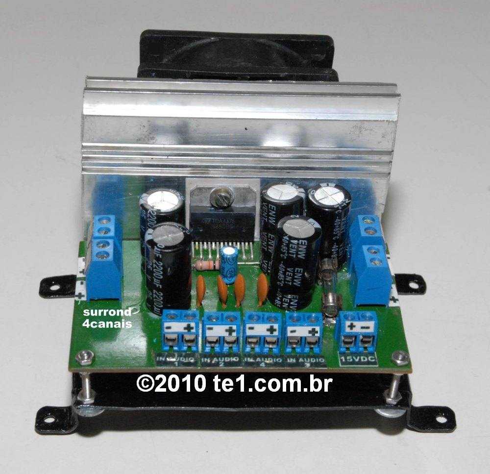
IC TDA7375 amplifier circuit diagram with PCB. Circuit of quadruple audio amplifier using integrated circuit TDA7375a audio amplifier for systems surround. Circuit of quadruple amplifier for systems surround using the ci tda7375, for potency of 7 watts for channel in the version amplifying quad or 15 watts in the dual version (stereo). Could arrive to 35 watts in the version.
The TDA7375AV is a technology class AB car radio amplifier able to work either in dual bridge or quad single-ended configuration. The exclusive fully complementary structure of the output stage and the internally fixed gain guarantee the highest possible power performances with extremely reduced component count.
The on-board clip detector simplifies gain compression operation. The fault diagnostics makes it possible to detect mistakes during car radio set assembly and wiring in the car.

All features
- High output power capability2 x 43 W max./4 Ω
- 2 × 37 W/4 Ω EIAJ
- 2 × 26 W/4 Ω @14.4 V, 1 kHz, 10%
- 4 × 7 W/4 Ω @14.4 V, 1 kHz, 10%
- 4 × 12 W/2 Ω @14.4 V, 1 kHz, 10%
- Minimum external components count:No bootstrap capacitors
- No Boucherot cells
- Internally fixed gain (26 dB BTL)
- Standby function (CMOS compatible)
- No audible pop during standby operations
- Diagnostics facility for:Clipping
- Out to GND short
- Out to VSshort
- Soft short at turn-on
- Thermal shutdown proximity
- Protections:Output AC/DC short circuit: to GND, to VS and across the load
- Soft short at turn-on
- Overrating chip temperature with soft thermal limiter
- Load dump voltage surge
- Very inductive loads
- Fortuitous open GND
- Reversed battery
- ESD
Operation of the circuit of the audio amplifier with tda7375
The capacitor C8 uncouples the internal tension divisor. The capacitors C5 and C6 are the filter for Power supply. The capacitors of 2200µF / 25V are the output capacitors. Vs is the Power supply that can be a car battery or a supply of 14 volts.
IC TDA7375 amplifier circuit diagram schematic

Power supply for the circuit
It can be with a transformer 12V/30VA, a rectifier bridge and a capacitor electrolytic of 4700µF or (larger). The maximum consumption of current with loads of 4 Ohms is 2.1 A. You can use loads of 2 ohms, but he/she also remembers to increase the size of the of heat-sink because the circuit integrated in Multiwatt package it will heat up a little more.
TDA7375 amplifier PCB, printed circuit board


Information on assembly of the circuit audio amplifier
When assembling the circuit, remember that this quadruple amplifier presents the channels two and four inverted, then you must connect the speakers with the inverted polarity in these outputs, in attention to the polarity of the electrolytic capacitors that must be of good quality.
Block diagram of TDA7375 for more information see the datasheet in PDF format of integrated circuit TDA7375
TDA7375 Pinout

Quad, stereo and 2.1 connection scheme

Standard board connection, connect jumper J1 and J2 as indicated in red.

To switch on this mode connect jumper J1 and J2 as indicated in red. You should also connect the terminals of capacitors C9 and C10. If you prefer they can be omitted. So can C2 and CN4.

In this mode you should connect the jumper cables as indicated in red. The 2,200uF capacitors are not required. However, if you intend to use it in quad mode in the future, make a jumper with a piece of wire at the bottom of the board, under the capacitors and 2.200uF. The audio inputs will be on the CN1 and CN₂ connectors. The audio output will use 2 connectors. If you prefer you do not need to install C9, C10, C11, C12, Cn4, Cn6, C2, C4.
BOM for mounting or amplifier.
Last Update: 07/28/2021 22:43
| Part | Value | Description | Quantity |
| Resistors 1/4W | |||
| R1 | 10k | Brown, black, orange, gold | 1 |
| Capacitors | |||
| C1, C2, C3, C4 | 470n/63V | Polyester capacitor | 4 |
| C5 | 1.000uF/25V | Electrolytic capacitor | 1 |
| C6 | 100nF | Ceramic Capacitor | 1 |
| C7 | 10uF/25V | Electrolytic capacitor | 1 |
| C8 | 47uF/25V | Electrolytic capacitor | 1 |
| C9, C10, C11, C12 | 2.200uF/25V | Electrolytic capacitor | 4 |
| Semiconductors | |||
| CI1 | TDA7375AV | 4-channel audio amplifier IC | 1 |
| Miscellaneous | |||
| CN1 | OUT1 — Output 1 | Terminal block 2 pin 5.08 mm | 1 |
| CN2 | OUT2 — Output 2 | Terminal block 2 pin 5.08 mm | 1 |
| CN3 | IN1 — Input 1 | Terminal block 2 pin 5.08 mm | 1 |
| CN4 | IN2 — Input 2 | Terminal block 2 pin 5.08 mm | 1 |
| CN5 | IN3 — Input 3 | Terminal block 2 pin 5.08 mm | 1 |
| CN6 | IN4 — Input 4 | Terminal block 2 pin 5.08 mm | 1 |
| CN7 | DC — Power Suply | Terminal block 2 pin 5.08 mm | 1 |
| CN8 | OUT3 — Output 3 | Terminal block 2 pin 5.08 mm | 1 |
| CN9 | OUT4 — Output 4 | Terminal block 2 pin 5.08 mm | 1 |
| J1, J2 | Pin header 3 pin | Operation Mode Selection | 2 |
| J3 | Jumper | 20 mm piece of component terminal or wire | 1 |
| Solder, Wires, PCB, Box, power supply. | |||
Download complete package – Datasheet + schematics + boards in PDF, PNG and updated with Gerber
Download PDF Mirror
Download PDF IC TDA7375, tda7375v, tda7375a, TDA7375AV
Buy TDA7375/77/79 diy kits in AliExpress – Worldwide free shipping

i wouldnt make the tracks to C1 C3 and C4 so narrow. It makes the etching almost doomed to failure for most enthusiasts. Better to replace those bits of track with a jump wire between two spacious points. I can recommend this because I tried etching the board as above and fucked it up.
cliare pcb drowing for tda7375
Good assembly of the circuit
Ola Toni.. eu estava pensando em montar este projeto surrond,
mas este layout ai esta de pessima qualidade, tem um borrado ai ligando gnd e o pino do ci que não da pra saber o que é isso, se é mesmo uma trilha ou borrado, se vc puder dar uma verificada nisso eu agradeço.att