Table of Contents
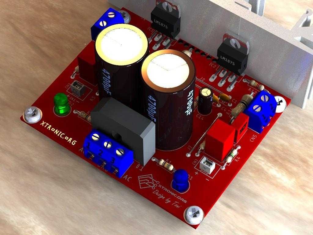
lm1875 amplifier circuit diagram stereo 2x 30W. This is an audio amplifier circuit using integrated LM1875 stereo to 2 × 30 Watts. With power supply for ease of assembly for any hobbyist. With a power of up to 20 Watts stereo amplifier that is suitable for use as power audio amplifier in various applications such as power amplifier for PC audio, FM radio, MP3 speaker, finally you’re sure to find great uses for this amplifier with LM1875 easy to assemble.
This is a circuit that has a while that was here in the drafts of the blog, so this early morning “without sleep” I decided to complete the article. This is a stereo audio amplifier circuit using integrated LM1875 for 2 × 30 Watts, as usual now in the new circuits this also comes with the source circuit to facilitate assembly for any hobbyist. With a power of up to 30 Watts per channel, this amplifier is suitable for use as a power stage in various applications as an amplifier for PC speakers, active speakers, surround sound, FM radio, MP3 player. It can also be used to tune those USB boxes, and the user will certainly find great uses for this amplifier with LM1875T stereo of easy assembly.
The LM1875 is a monolithic power amplifier offering very low distortion and high-quality performance for consumer audio applications.
The LM1875 delivers 20 watts into a 4 or 8 load on ±25V supplies. Using an 8 load and ±30V supplies, over 30 watts of power may be delivered. The amplifier is designed to operate with a minimum of external components. Device overload protection consists of both internal current limit and thermal shutdown.
The LM1875 design takes advantage of advanced circuit techniques and processing to achieve extremely low distortion levels even at high output power levels. Other outstanding features include high gain, fast slew rate and a wide power bandwidth, large output voltage swing, high current capability, and a very wide supply range. The amplifier is internally compensated and stable for gains of 10 or greater.
- Up to 30 watts output power
- AVO typically 90 dB
- Low distortion: 0.015%, 1 kHz, 20 W
- Wide power bandwidth: 70 kHz
- Protection for AC and DC short circuits to ground
- Thermal protection with parole circuit
- High current capability: 4A
- Wide supply range 16V-60V
- Internal output protection diodes
- 94 dB ripple rejection
- Plastic power package TO-220

About the amplifier circuit:
The project relies on a symmetrical type power supply and a double transformer from 9 to 18 VAC can be used, the filter capacitors (C5 and C6) can be from 2,200uF to 6,800uF. The rectifier bridge can be KBL406 or equivalent.
At the audio input C9 and R5 form a high pass RC filter, where R5 also determines the input impedance, the cutoff frequency will be 3.2 Hz. Resistor R7 and capacitor C11 form a low-pass filter, to avoid RF signals in the amplifier, and the cutoff is at 482.5 KHz, just below the AM band.
Schematic lm1875 amplifier circuit diagram stereo 2x 30W

Suggested printed circuit board PCB lm1875T amplifier circuit stereo 2x 30W


BOM to assemble the power amplifier with LM1875 IC.
Last Update: 09/14/2021 12:55 PM
| Part | Valor | Description | Quantity |
| Capacitors | |||
| C1, C2, C3, C4 | 100nF | Ceramic Capacitor | 4 |
| C5, C6 | 4700µF/35V | Electrolytic capacitor | 2 |
| C9, C10 | 2.2µF | Polyester capacitor | 2 |
| C11, C12 | 330pF | Ceramic Capacitor | 2 |
| C13, C14 | 47µF/35V | Electrolytic capacitor | 2 |
| C15, C16 | 220nF | Polyester capacitor | 2 |
| Semiconductors | |||
| B1 | KBL406 or equivalent | Bridge rectifier | 1 |
| IC1, IC2 | LM1875 or LM1875T | Audio amplifier integrated circuit. | 2 |
| LED1, LED2 | Red Led 5 mm | LED 5 mm | 4 |
| Resistors 1/4W | |||
| R1, R2 | 10k | Brown, Black, Orange, Gold | 2 |
| R3, R4 | 1M | Brown, Black, Green, Gold | 2 |
| R5, R6, R11, R12 | 22k | Red, Red, Orange, Gold | 4 |
| R7, R8, R9, R10 | 1K | Brown, Black, Red, Gold | 4 |
| R13, R14 | 1 Ohm / 2W | Brown, Black, Gold, Gold | 2 |
| Miscellaneous | |||
| CN1 | AC | Terminal block 2 pin 5.08 mm | 1 |
| CN2 | IN1 | 2.54 mm 2-way JST Male Connector 2.54 mm | 1 |
| CN3 | IN2 | 2.54 mm 2-way JST Male Connector 2.54 mm | 1 |
| CN4, CN5 | OUT-L | Terminal block 2 pin 5.08 mm | 2 |
| Solder, Wires, Box, Solder, Heat sink for the IC, PCB, etc. | |||
Download PDF, PNG, Postscript Gerber files for assembling the power amplifier with LM1875 IC
Download PDF
Download the PDF datasheet of the LM1875 IC
Download PDF datasheet of the KBL406 rectifier bridge


jesus christ wtf is this? right input goes to ground :D
This schematic is incorrect. R5 and R11 should go from pin 4 to pin 2 of their respective ICs, not the junction of the 10k resistor and the 2.2uf capacitor. Also, much better performance can be achieved using a centre-tapped transformer and dual-ended supply. See the datasheet’s typical application schematic.
hi i have problem i don’t have any voice and should i put capacitor c10 or not?
There is an error r5 and r11 220k must connect straight to pin 2 off ic1 and ic2.
hello hi do you have WhatsApp or something else to help me thanks a lot
after making this circuit when i give power,there is a bang voice,what is the reason..plz guide
sir
i need help regarding soldering diode whichis with right side of 1R resitor,should it be sold with +ve
please print circuit pdf file. thank you!
Trafo 12 V ct or 12V simetris please,
12v dc amplifier stereo audio top hi fi power sistem please sir my numbers 09417825411, 09417812056 please back call me
Why my left out make noisy sound, but the right one dont issue anything. That problem can be related with suuply?
Help !!!!!!!!!!
Hey …..
Very good,that’s like a professional project.Easy to make,assemble,looking beautiful….
Thanks…..