Table of Contents
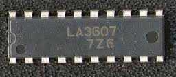
Circuit of graphic equalizer of 7 bands using it integrated la3607 of Sanyo. The circuit integrated la3607 allows to just set up a graphic equalizer of 7 bands for a channel adding some capacitors and variable resistors to the circuit.
The cut frequency can be adjusted using variable resistors. It possesses high stability for loads capacitive. To be necessary of more channels is to set up how many units they are only necessary.
The circuit of the equalizer multi band with having integrated la3607
That is basic application proposed by Sanyo, where the resonance frequency for each strip was fastened as:
Fo: 60Hz, 150Hz, 400Hz, 1KHz, 2.5kHz, 6KHz, 15KHz
Fo is calculated using the following formula:
Fo=1/2π√C1.C2.R1.R2
Q (quality Factor)
Q is calculated using the following formula:
Q=√C1.R2/C2.R1
The work tension for the circuit is between 5 and 15 volts
Schematic for circuit


pl provide LA3600 PCB
Hello HK
http://radiomaster.com.ua/2308-7-i-polosnyy-mono-ekvalayzer-na-la3607.html
need pcb ??? Help me
were is the la3607 chip avalable