Table of Contents
Digital inductimeter (inductor meter) transform your multimeter in a simple and cheap inductor meter. Measure inductors with this instrument Simple, Good and cheaply
In the ARRL Handbook a very simple circuit to measure inductors.
This Inductimeter measures inductors between 3µH and 7mH, in two measurement scales. The reading of the inductance is made in the scale of miliVolts of a multimeter. The precision of this Inductimeter is around +/- 10%, what is adapted perfectly to the experimental character of the radio amateurism. The multimeter should be digital. Measure of reels is a thing that we hardly heard to speak, until it seems that how many is the value of reels you exhale she has, but inductors has your unit of measure Henry.
With that circuit, I think can aid in the assemblies of circuits of RF.
The Circuit of the inductor meter for multimeter
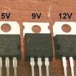
The circuit of the meter is composed by the following blocks: Feeding source, Oscillator, Differentiating, Integrator and Adjustment of Offset. The feeding source is composed by a pile of 9V and a circuit integrated tension regulator (U2). To increase the useful life of the pile we chose the regulator 78L05 that has a current quiescent around 3mA. A regulator of the type 7805 already has a current quiescent around 10mA (some manufacturers’ regulators get to present even to 25mA of current quiescent!).
The oscillator (U1:D), that it supplies the pulses for the differentiating, it generates pulses in two fixed frequencies. These frequencies determine the measurement scales. The first scale, with the oscillator in 60KHz, is going from 3µH to 500µH. In the second it climbs, from 100µH to 7mH, the oscillator works with a frequency of 6KHz. The selection of scales is given by the key, S1, of the type 2 poles 2 positions. This oscillator is of the type RC with a gate INVERTERS (U1:D) and with a buffer (U1:C) to isolate him of the load RL.
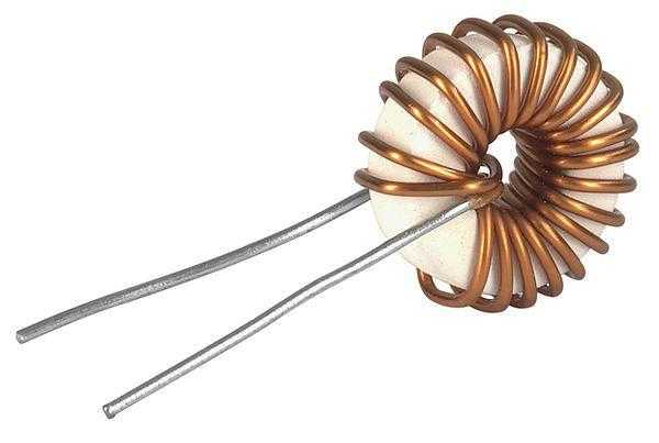
The differentiating is formed by a load resistive R and for the inductor to be measured, L. In this differentiating one pulses will be generated whose width depends of the constant of time RL, like R it is fixed, as larger the inductor L,
The pulses of the differentiating are applied to the entrance of the following logical door (U1:B), that it transforms these analogical pulses and level pulses TTL, e of this proceeds for the last door logic (U1:A) and RC formed by R3 and C3—the integrator that transforms these pulses in a tension proportional dc the width of these pulses.
Last, the circuit of offset Adjustment generates a small tension to zero the instrument in the scale from 3µH to 500µH.
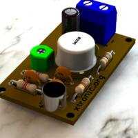
Assembly and Calibration for Inductimeter digital
The assembly of the circuit is simple. We advised to use a socket of 14 pins for the integrated circuit. The connections between Inductimeter and the inductor under measurement should be maintained short, for not affecting the measured value.
For the calibration, it is necessary to have an inductor (it winds) pattern. This will determine the precision of Inductimeter. The procedure that we described is for a standard inductor of 330µH.
Select the scale of low measurement (3 to 500µH), place the measurement terminals in short-with a piece of thread of enough size just to establish the short circuit. Tie the exit in the multimeter and select the miliVolts scale. Adjustment of the potentiometer to read 0V in the multimeter. Remove the short circuit and place the standard inductor to be measured. Adjustment the trimpot (R2) of the scale of low measurement to read 330 mV in the multimeter. Ready, this scale is gauged.
To gauge the other scale, select the scale of high measurement. Place the standard inductor to be measured. Adjustment of the trimpot of the scale of high measurement (R5) to read 0,33 mV in the multimeter. Inductimeter is gauged.
Remind that in the scale lowers the miliVolts read in the multimeter they indicate µH and in the scale high the miliVolts read in the multimeter they indicate mH.
Whenever it will measure in the low scale, it is necessary to place a short one in the place of the inductor under measurement and to adjust the potentiometer to read 0V in DVM.
Modifications and improvements for circuit
Certainly, an external source can be implemented, especially for those that use this Inductimeter for long periods. This source should supply being 9 and 12Vdc (continuous current!). The consumption current is low, smaller than 50mA.
The circuit integrated used it is a door mounted NAND as INVERTER, in your place an INVERTER can be used, however we verified that this door NAND, of the type HC, is easier to find in the trade. The important is to use a door type HC because it works with a smaller current, increasing the useful life of the pile.
It is not advisable to use a measurement cable because it can alter the measured values.
Finally your inductor meter digital
This circuit cannot lack in the supported of whom it makes maintenance, or it likes to do assemblies of transmitters and receivers. Same, being simple and cheap, it offers an appropriate precision to this end.

Bibliography: ARRL Handbook goes Radioamateurs 1999