Table of Contents
Download Atanua real-time logic simulator – basic boolean logic. Atanua is a real-time logic simulator, designed to help in learning of basic boolean logic and electronics. It uses OpenGL hardware-accelerated rendering and a custom UI designed for a fast workflow and a very low learning curve, letting the students concentrate on learning the subject instead of spending time learning the tool.

Features Atanua real-time logic simulator
- Intuitive, hardware-accelerated interface.
- Available for Windows, Linux and Mac os X.
- Real-time logic simulation (at 1000Hz).
- Most common logic blocks, with both US and Finnish symbols.
- Simulation of various 74-series chips.
- Simulation of a 8051 microcontroller variant.
- Input through keyboard-bound buttons, output through various LEDs and 7-segment displays.
- Plug-in interface for creation of custom parts.
- Instant feedback through wire colors, which show signal states and error states.
- Helpful tooltips.
- Anti-cheating tool available for teachers for homework validation.
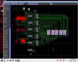
Wire colors show the state of the connection.
- Gray wire means there’s no signal input.
- Red means there’s more than one signal input, or something else is wrong.
- Bright green is signal high.
- Dark green is signal low.
Base parts list Atanua real-time logic simulator
- Logic ‘0’ (ground) and ‘1’ (vcc)
- Logic AND, OR, NAND, NOR, XOR and NOT gates, in both US and Finnish symbols
- SR-latch (NOR and NAND versions), Synchronized SR-latch, D-latch, T-latch, JK-latch
- JK-flipflop, D-flipflop, T-flipflop, SR-flipflop
- 2-bit MUX block, 3-bit DX-block
- Synchronized clock generators (0.1Hz, 0.2Hz, 0.5Hz, 1Hz, 2Hz, 5Hz, 10Hz, 20Hz, 50Hz, 100Hz, 200Hz, 500Hz)
- Labels
Chips list:
- 2051 – 20-pin 8051-variant 8-bit Microcontroller with 2K Bytes Flash and 15 Programmable I/O Lines
- 2708 – 1024-word by 8-bit erasable programmable read only memories
- 2716 – 2048-word by 8-bit erasable programmable read only memories
- 2732 – 4096-word by 8-bit erasable programmable read only memories
- 7400 – Quad 2-input NAND Gate
- 7402 – Quad 2-input NOR Gate
- 7404 – Hex Inverter
- 7408 – Quad 2-input AND Gate
- 7410 – Triple 3-input NAND Gate
- 7420 – Dual 4-input NAND Gate
- 7432 – Quad 2-input OR Gate
- 7447 – BCD to 7-segment Decoder/Driver
- 7473 – Dual J-K Flip-Flop with Clear
- 7474 – Dual D Positive Edge Triggered Flip-Flop with Preset and Clear
- 7485 – 4-bit Magnitude Comparator
- 7486 – Quad 2-input XOR Gate
- 7490 – Decade Counter (separate Divide-by-2 and Divide-by-5 sections)
- 74138 – 3 to 8-line Decoder/Demultiplexer
- 74139 – Dual 2 to 4-line Decoder/Demultiplexer
- 74151 – 8-Line to 1-Line Data Selector/Multiplexer
- 74154 – 4-Line to 16-Line Decoder/Demultiplexer
- 74181 – 4-bit Arithmetic Logic Unit and Function Generator may contain some bugs due to complexity of the chip)
- 74191 – Synchronous Up/Down Binary Counter
- 74192 – Synchronous Up/Down Decade Counter (some border cases may act differently from hardware; not well-defined in data sheet)
- 74193 – Synchronous Up/Down Binary Counter
- 74195 – 4-bit Parallel-Access Shift Register
- 74240 – Octal Buffer with Inverted Three-State Outputs
- 74241 – Octal Buffer with Noninverted Three-State Outputs
- 74244 – Octal Buffer with Noninverted Three-State Outputs
- 74245 – Octal Bus Transceiver with Noninverted Three-State Outputs
- 74163 – Synchronous 4-bit Binary Counter with Synchronous Clear
- 74164 – 8-bit Parallel-Out Serial Shift Register with Asynchronous Clear
- 74165 – Parallel-Load 8-Bit Shift Register
- 74283 – 4-bit Binary Full Adder
- 74574 – Octal D-Type Edge-Triggered Flip-Flop with Three-State Outputs
I/O parts list:
- LEDs (red, green, blue, cyan, magenta, yellow, white), normal and inverted
- 7-segment displays in same colors, normal and inverted
- 309, numeric display with logic
- Keyboard keys (0,1,2…9, a,b,c…z)
- Simple logic probe
- Simple audio output
- Unipolar and bipolar stepper motors


Hi Adam, You can connect a 12 or 18V DC source in the power connector, do not worry about polarity.