Table of Contents
lm386 audio amplifier circuit diagram with PCB, the LM386 is a power amplifier designed for use in low voltage consumer applications. The gain is internally set to 20 to keep external part count low, but the addition of an external resistor and capacitor between pins 1 and 8 will increase the gain to any value from 20 to 200. The inputs are ground referenced, while the output automatically biases to one-half the supply voltage. The quiescent power drain is only 24 milliwatts when operating from a 6 volt supply, making the LM386 ideal for battery operation.
The LM386M-1 and LM386MX-1 are power amplifiers designed for use in low voltage equipment. The gain is internally set to 20 to use few external components, but adding an external resistor and capacitor between pins 1 and 8 increases the gain to anywhere from 20 to 200.
LM386N-1, LM386N-3, LM386M-1, LM386MM-1 can use powe supply up to 12V and LM386N-4 up to 18V
Features:
- Battery operation
- Minimum external parts
- Wide supply voltage range: 4V-12V or 5V-18V
- Low quiescent current drain: 4mA
- Voltage gains from 20 to 200
- Ground referenced input
- Self-centering output quiescent voltage
- Low distortion: 0.2% (AV = 20, VS = 6V, RL = 8[Ohm], PO = 125mW, f = 1kHz)
- Available in 8 pin MSOP package
Applications
- AM-FM radio amplifiers
- Portable tape player amplifiers
- Intercoms
- TV sound systems
- Line drivers
- Ultrasonic drivers
- Small servo drivers
- Power converters
Equivalent Schematic lm386 pinout datasheet and Connection Diagrams LM386M-1, LM386MM-1, LM386N-1, LM386N-3 or LM386N-4
Application Hints
GAIN CONTROL
To make the LM386 a more versatile amplifier, two pins (1and 8) are provided for gain control. With pins 1 and 8 open the 1.35 kΩ resistor sets the gain at 20 (26 dB). If a capacitor is put from pin 1 to 8, bypassing the 1.35 kΩ resistor, the gain will go up to 200 (46 dB). If a resistor is placed in series with the capacitor, the gain can be set to any value from 20to 200.
Gain control can also be done by capacitive coupling a resistor (or FET) from pin 1 to ground. Additional external components can be placed in parallel with the internal feedback resistors to tailor the gain and frequency response for individual program.
For example, we can compensate poor speaker bass response by frequency shaping the feedback path. This is done with a series RC from pin 1 to 5 (paralleling the internal 15 kΩ resistor). For 6 dB effective bass boost: R. 15 kΩ, the lowest value for good stable operation is R = 10 kΩ if pin 8 is open. If pins1 and 8 are bypassed, then R as low as 2 kΩ can be used. This restriction is because the amplifier is only compensated for closed-loop gains greater than 9.
Schematic of power audio amplifier for applications as Amplifiers of radio FM, Amplifiers of MP3 portable players, Intercoms, Systems of sound of TV and other applications.
lm386 audio amplifier circuit diagram schematic
The power supply for this circuit should be 3 to 12 volts.
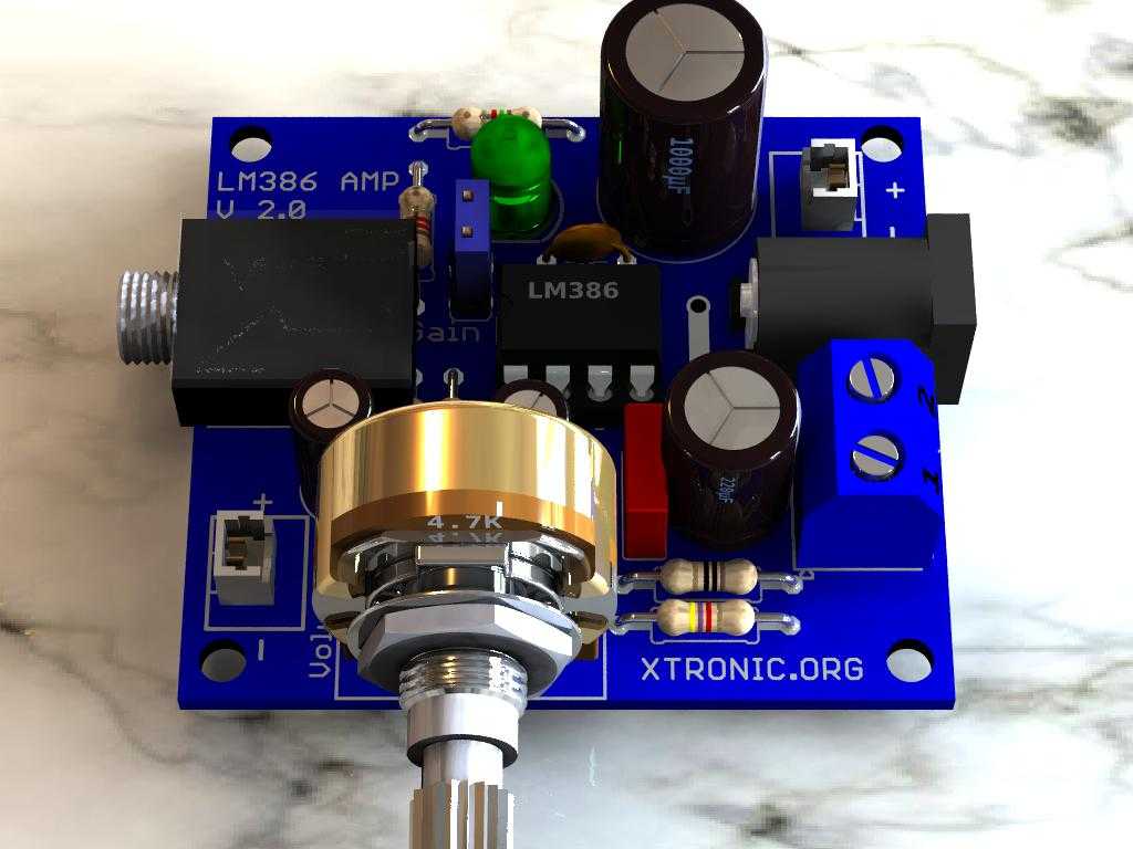
Suggestion of printed circuit board PCB
Part List for the LM386 Amp
| Part | Value |
| Resistors 1/4W 5% | |
| R1 | 10 — Brown, Black, Gold, Gold |
| R2 | 1.2k — Brown, Red, Red, Gold |
| R3 | 4.7K — Yellow, Violet, Red, Gold |
| R4 | 1.5K — Brown, Green, Red, Gold (Optional) |
| R5, R6 | 10K — Brown, Black, Orange, Gold |
| Capacitors | |
| C1, C6 | 10µF/16V — Electrolytic capacitor |
| C2 | 220µF/16V — Electrolytic capacitor |
| C3 | 100n — Ceramic or polyester capacitor |
| C4 | 1000µF/16V — Electrolytic capacitor |
| C5 | 100n — Ceramic Capacitor |
| Semiconductor | |
| IC1 | LM386n – DIP8 audio amplifier IC |
| Connectors | |
| J2 | P2 connector – audio input. |
| J1 | Jack Connector – DC Power |
| CN1 | Audio input connector (optional) |
| CN2 | Power connector (Optional) |
| JP1 | Gain adjustment jumper (optional) |
| LED1 | Red LED 5 mm (Optional) |
| CN3 | Terminal block 2 pin 5.08 mm |
| Miscellaneous | |
| P1 | Simple Potentiometer 4.7K to 10K |
| 4.5 to 12V /1A power supply | |
| PCB, solder, wires, Box, knob, etc. | |
Last update: 04/08/2021 16:34
Download the circuit PCB in PDF, PNG and Gerber
Download PDF
If you liked this one, then check out the new version, stereo and with power supply design.

ola Toni posso saber qual a medida da pcb obrigado
Very Good Website
Hello Vimuthu
Thanks your feedback!
Thanks!
where do i buy these board for the lm386 amplifier
Hello Gene
In Aliexpres
http://www.anrdoezrs.net/links/5042208/type/dlg/http://www.aliexpress.com/af/tda7294-amplifier.html?ltype=wholesale&SearchText=lm386+amplifier&d=y&origin=n&initiative_id=AS_20151226120124&catId=0&isViewCP=y
Hello
Please send the pcb layout and dimensions