Table of Contents
TDA2009 amplifier circuit diagram, stereo TDA2009A. The TDA2009A is class AB dual Hi-Fi Audio power amplifier assembled in Multiwatt package, specially designed for high quality stereo application as Hi-Fi and music centers.
Characteristics
- High output power
- (10 + 10w min. @ d = 1%)
- High current capability (up to 3.5a)
- Ac short circuit protection
- Thermal overload protection
- Space and cost saving : very low
- Number of external components
- And simple mounting thanks to the
- Multiwatt package.
Build-in protection systems
Thermal shut-down
The presence of a thermal limiting circuit offers the following advantages:
1) An overload on the output (even if it is permanent), or an excessive ambient temperature, can be easily withstood.
2) The heatsink can have a smaller factor of safety compared with that of a conventional circuit. There is no device damage in the case of excessive junction temperature : all that happen is that Po (and therefore Ptot) and Io are reduced.
The maximum allowable power dissipation depends upon the size of the external heatsink (i.e., its thermal resistance);
Short circuit (AC Conditions).
The TDA2009A can withstand an accidental short circuit from the output and ground made by a wrong connection during normal play operation.
Mounting instructions
The power dissipated in the circuit must be removed by adding an external heatsink.
Thanks to the MULTIWATT package, attaching the heatsink is very simple, a screw or a compression spring (clip) being sufficient. Between the heatsink and the package it is better to insert a layer of silicon grease, to optimize the thermal contact, no electrical isolation is needed between the two.
Schematic of the power sound amplifier stereo with tda2009

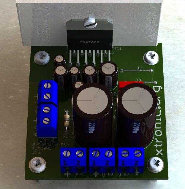
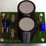
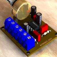
PCB for the amplifier stereo with tda2009


The power source is from 12 to 18 volts max. with current of 2 amperes.
BOM of the amplifier stereo with tda2009
Part List
| Components | Value |
| Capacitors | |
| C1, C2 | 2.2µ Capacitor electrolytic |
| C3 | 22u Capacitor electrolytic |
| C4, C5 | 220u Capacitor electrolytic |
| C6 | 100u Capacitor electrolytic |
| C7, C8, C9 | 100n Capacitor polyester – 104 , 100n or 0.1 |
| C10, C11 | 2200u Capacitor electrolytic |
| Semiconductors | |
| IC1 | TDA2009A |
| Connectors | |
| IN-L | Terminal block connector 2 screws – Left Audio input |
| IN-R | Terminal block connector 2 screws – Right Audio input |
| OUT-L | Terminal block connector 2 screws – Left Audio Output |
| OUT-R | Terminal block connector 2 screws – Right Audio Output |
| VCC | Terminal block connector 2 screws – Power supply connector |
| J2 | Jumper 12 mm |
| J3 | Jumper 12 mm |
| Miscellaneous | Printed Circuit Board, Welding, Wires, Box, etc. |
| Resistors |
|
| R1, R3 | 1k3 Value not commercial, use 1k2 – Black, Red, Red, Gold |
| R2, R4 | 18 Ohms – Brown, Gray, Black, Gold |
| R5, R6 | 1 Ohm – Brown, Black, Gold, Gold |
All capacitor voltage
Power supply ≥ 18V = Capacitors 25V
Power supply ≤19V capacitors 35V
Download the printed circuit boards in PDF, PNG and Gerber for the Amplifier Circuit.
Download TDA009 PDF Datasheet ST
See also the stereo amplifier with the same IC


I try this sir twice. Doesn’t work. Help.
Sir Good Day, I build this project, but It did’nt work. please help me how to do it. my pcb layout was correct and schematics also. can you show me a finished and working hardware of this circuit please? thanks in advance