Table of Contents
Circuit spy bug BF494 FM transmitter 2 transistors. That small circuit transmitter (SpyToni) it is ideal for ready espionage for strip from radio Fm or receiver of VHF. Of course the recreational purpose also exists, and the children will adore to have a transmitter that allows to speak for a radio FM placed at distant place and like this pretend the secret agent.
")
Operation of the FM transmitter with bf494
The signs captured by the electret microphone, your voice or close people’s chats, they are mischievous to the base of the transistor Q1 through C1 where it is amplified. The resistor R2 together with R3 it determines this amplification.
Wanting a smaller earning because the sound tends to be distorted by the excessive earnings, we can reduce the value of R2 and R3.
After having amplified, the sign is removed of the collector of this transistor and mischievous to the base of Q2, where it modulates in frequency the sign generated by this stage. This stage is precisely an oscillator of high frequency that operates in the strip of FM. Your frequency is determined by L1 and for the adjustment of CV.
The obtained signs, already modulated in frequency, they are mischievous to a linked antenna in the collector of the transistor Q2.
The reach of the transmitter will depend a lot on this antenna, of the feeding of the circuit and of the place where it will happen your operation. In open field, with a feeding of 6 V (4 piles AA) and an antenna of about 40 cm of length, we can arrive to the 200 meters.
With a smaller antenna, or in place with many structures of iron (flagstones) the reach will be sensibly reduced. A common wall without metallic structure is not obstacle for this transmitter.
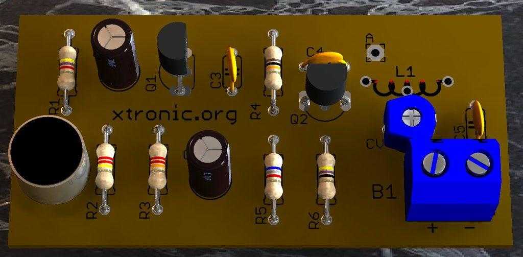
Printed circuit board


List material for assembly of the micro fm transmitters with bf494
Semiconductors:
- Q1 – BC558
- Q2 – BF494
- MIC–microphone electret two terminals
Resistors: (1/4 W, 5%)
- R1–4,7 KΩ (Yellow, violet, Red, Gold)
- R2–220 KΩ (red, red, yellow, Gold)
- R3–22 KΩ (red, red, orange, Gold)
- R4–10 KΩ (Brown, black, orange, Gold)
- R5–6,8 KΩ (Blue, Gray, red, Gold)
- R6–47 Ω (Yellow, violet, Black, Gold)
- C1–10 µF/16 V – ELECTROLYTIC
- C2–4,7 µF/16 V – ELECTROLYTIC
- C3–10 nF – ceramic
- C4–4,7 pF – ceramic
- C5–100 nF – ceramic
- CV–trimmer from 3-30 to 5-50 pF
Miscellaneous:
- L1 – see text
- S1–simple Switch
- B1 –3 to 6 V – Battery or power supply
- ANT –antenna – to see text
Printed circuit board, box for assembly, battery holder for 2 or 4 small Batteries, etc.
Download PDF files – PCB for FM transmitter
Mirror