Table of Contents
That project is of a FM spy bug transmitter with bf494, easy assembly, so that anyone can obtain success in your assembly.
Operation of the circuit of the FM spy bug transmitter with transistor bf494
The circuit diagram is basic of low-power FM micro-transmitters. Where it consists of a high-frequency oscillator. This frequency is determined by the resonant circuit L / CV, CV is a can be set so that the oscillator covers the range of FM.
The feedback to maintain the oscillation comes from the capacitor of 4.7 pF, the capacitor in parallel with the source is to do the decoupling.
The audio is picked up by a sensitive two-terminal electret microphone and coupled to the base of transistor bf494 via capacitor C5.
This signal modulates the circuit. The antenna for the circuit is a piece of hard-wire of +/- 20 cm.
To test the transmitter, connect an FM radio and tune to a free-range, then adjust the trimmer with a plastic key until you pick up a stronger signal, when you tune in a stronger signal away from the radio if the signal disappears it reverts to the tune until you get a signal stronger.
The components for assembly of the fm spy bug transmitter with bf494
The transistor bf494 can be replaced by the bf495 without problems, this transistor easy to be found in the trade.
In attention with the value of the capacitors so that there is no change of position, C1, C2, C3, C5 must be ceramic.
CV is a trimmer for 3 to 30 pF. Can be ceramic or plastic.
L is the coil, consists of 4 turns of 20 AWG wire, air core.
Schematic FM transmitter with transistor

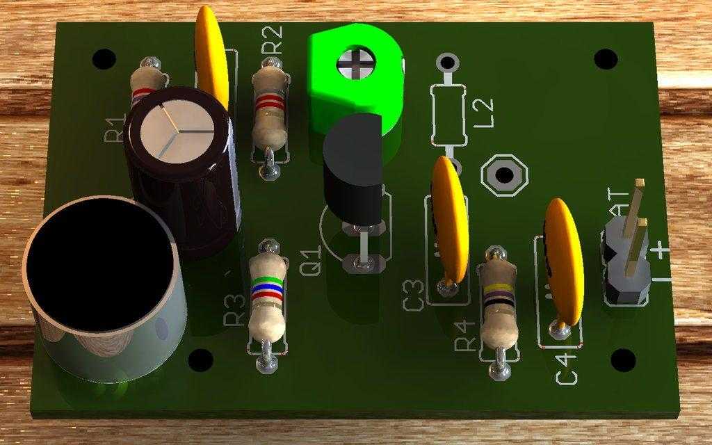
Suggestion of Printed circuit board for fm bug circuit


Part list for FM transmitter bug
| Parts |
Value |
| BAT |
Two to four batteries (3 to 6 volts) |
| C1 |
47nF (47n, 473, 0.047) |
| C2 |
4,7pF (4.7, 4p7, 4r7) |
| C3 |
100nF (104, 100n, 0.1) |
| CV1 |
3pF – 30pF |
| T1 * |
bf494 or equivalent * |
| L1 * |
See text |
| MIC |
Electret microphone |
| R1 |
2k7 (red, violet, red, gold) |
| R2 |
8k2 (gray, red, red, gold) |
| R3 |
5k6 (green, blue, red, gold) |
| R4 |
47 (yellow, violet, black, gold) |
*See text.
Download the files the PDF board for this assembly.
Gerber added
Mirror
- Download BF494 transistor PDF datasheet
- Download BF495 transistor PDF datasheet
- Download PDF datasheet of Murata ceramic trimmer/a>


It is work?