Table of Contents
Circuit MAX4410 Headphone circuit diagram amp driver Evaluation kit, based on the Maxim Integrated MAX4410 Evaluation Kit, which is designed to be used in portable equipment on boards with little space… The MAX4410 stereo headphone driver is designed for portable equipment where board space is at a premium. The MAX4410 uses a unique DirectDrive architecture to produce a ground-referenced output from a single supply, eliminating the need for large DC-blocking capacitors, saving cost, board space, and component height.
The MAX4410 delivers up to 80mW per channel into a 16 Ω load and has low 0.003% THD+N. A high power-supply rejection ratio (90dB at 1kHz) allows this device to operate from noisy digital supplies without an additional linear regulator. The MAX4410 includes ±8kV ESD protection on the headphone outputs. Comprehensive click-and-pop circuitry suppresses audible clicks and pops on startup and shutdown. Independent left/right, low-power shutdown controls make it possible to optimize power savings in mixed mode, mono/stereo applications.
The MAX4410 operates from a single 1.8V to 3.6V supply, consumes only 7mA of supply current, has short-circuit and thermal overload protection, and is specified over the extended -40 °C to +85 °C temperature range. The MAX4410 is available in a tiny (2 mm x 2 mm x 0.6 mm), 16-bump chip-scale package (UCSP™) and a 14-pin TSSOP package.
Key Features Circuit MAX4410 Headphone circuit diagram amp driver Evaluation kit
- No Bulky DC-Blocking Capacitors Required
- Ground-Referenced Outputs Eliminate DC-Bias Voltages on Headphone Ground Pin
- No Degradation of Low-Frequency Response Due to Output Capacitors
- 80mW Per Channel into 16 Ω
- Low 0.003% THD + N
- High PSRR (90dB at 1kHz)
- Integrated Click-and-Pop Suppression
- 1.8V to 3.6V Single-Supply Operation
- Low Quiescent Current
- Independent Left/Right, Low-Power Shutdown Controls
- Short-Circuit and Thermal Overload Protection
- ±8kV ESD-Protected Amplifier Outputs
- Available in Space-Saving Packages
- 16-Bump UCSP (2 mm x 2 mm x 0.6 mm)
- 14-Pin TSSOP
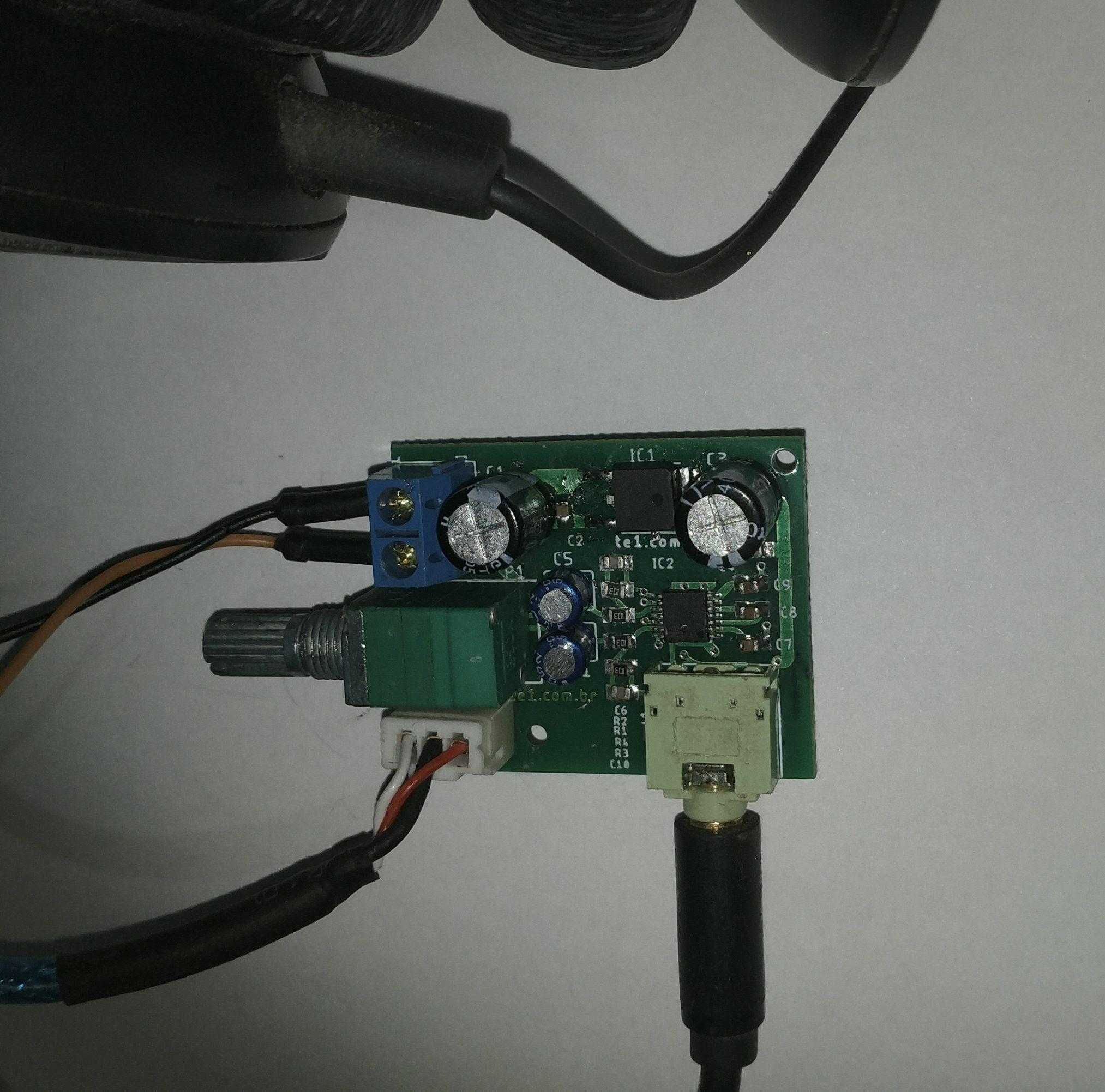
About our headphone amplifier circuit with IC Maxim MAX4410
Basic application of the document MAX4410 Evaluation Kit, added 3.3V voltage regulator circuit for the PCB to operate with voltages up to 9V or even a portable version for 4.1V batteries.
Schematic of the amplifier with MAX4410 (stereo headphone drive)

Printed Circuit Board Suggestion


BOM stereo headphone drive with IC MAX4410
| Parts | Value | description | quantity |
| Resistors | |||
| R1, R2, R3, R4 | 10K (103) | SMD Resistor 0805 | 4 |
| Capacitor’s | |||
| C1 | 1000µF/16V or 25V | Electrolytic Capacitor | 1 |
| C3 | 220uF or 470µF/6.8V or 10V | Electrolytic Capacitor low ESR | 1 |
| C2, C4 | 100n | SMD Capacitor 0805 X5R | 2 |
| C5, C11 | 1µF / 63 or 100V (105) | Polyester Capacitor | 2 |
| C6, C10 | 100p | SMD Capacitor 0805 NP0 | 2 |
| C7, C8, C9 | 2.2µ | SMD Capacitor 0805 X7R | 3 |
| Semiconductors | |||
| IC1 | LM1117DTX-3.3/NOPB or equivalent* | Voltage Regulator 3.3V SOT-223 or TO-252 | 1 |
| IC2 | MAX4410 | IC TSSOP14 stereo headphone drive Maxim integrated | 1 |
| Several | |||
| DC | Power supply | Connector 2.54 mm 2 pins | 1 |
| IN | Audio input | Connector 2.54 mm 3 pins | 1 |
| J1 | Audio output | Connector P2 3,5 mm | 1 |
| P1 | 50k (503) | Mini pot with switch | 1 |
| Welding, Wire, PCB, Box, power supply, etc. | |||
*Use AMS1117-3.3 for power supply ≤ 12V
Equivalent: see the datasheet for pinout
AMS1117CD-3.3, BL1117-33CY, BL1084-33-CY, AZ1084CD-3.3TRG1, AMS1086CD-3.3, LD1117AG-33-TN3-A-R, LM1117IDTX-3.3/NOPB, NCV4274ADT33RKG,
*Use HT7533-1 for power supply ≥ 12V, change C1 to 1000µF/25V
Equivalent: see the datasheet for pinout
BD3570FP-E2, ME1117A33K3G, ZLDO1117K33TC, NCP1117DT33RKG,
Download the PDF and Gerber files from the boards for this assembly