Table of Contents
TDA7294 amplifier 100W or TDA7293, bridge, or stereo dynamic also using the integrated circuit, TDA7295 or TDA7296 with protection circuit using CI UPC1237 (μPC1237), to use the bridge (mono), just close the circuit jumper.
About the TDA7293 or TDA7294 amplifier circuit with UPC1237 protection
Circuit with option to use ST Microelectronics integrated TDA729X circuits, in Ponte (Mono) or stereo application. An ideal dynamic amplifier to use in active boxes, power audio amplifier, home audio, etc.
Includes symmetric power supply circuit in the project, it requires a double transformer from 18 to 28V depending on the CI used. For source filter you can use capacitors of 4.700UF to 10,000UF with a diameter of up to 30 mm. The rectifier bridge may be GBJ2510 or equivalent.
The speaker protection circuit uses the integrated circuit UPC1237, although it is an old CI is still available for purchase. We use source to feed the protection circuit with D3 and D4 diodes, resistor R17 serves to limit the current in the relay circuit, CI μPC137 supports up to 60V. In our circuit we use the OMRON G2R-2-DC24 relay, conferring in the datasheet the coil has a resistance of 1100 ohms and 21.8 mA of current and 24V operating voltage with good tolerance. For our voltage divider, using 26V transformer, we have about 26V DC on the output.
For 26V = 100, use 100 Ohms
For 28V = 183, we will use 180 or 220 ohm resistors.
For 24V we will use a resistor of: 10 ohms.
C3 and C6 capacitor set the AC coupling for our amplifier and R2 and R6 set a circuit high pass filter, mainly influencing the low (severe) frequencies. Using 470NF capacitor according to the datasheet we have cut about 15hz, if you use 1UF capacitor we have 7hz. For 2.2uf capacitor, we have 3.2Hz.
The R1 and R3 resistor next to C5 and C8, set a low pass filter to maintain high frequency signs away from our power amplifier. For the values used, we have cut to about 1.8MHz. If you prefer, change the components with larger values and decrease the cutoff frequency.
The mute circuit was implemented according to circuit available in Datasheet, and C11 and C12 capacitors in conjunction with R11 and R7 are responsible for the time telling when turning on and off the amplifier and avoiding the “pop”.
The R5-R8 and R10-R13 resistor are responsible for the gain and as the circuit configuration is set to 30 dB, you can change these components to change the gain. However, it assesses that R5-R10 is of the same value as R 2-R 6.
The R2-R6 resistors are those that determine the input impedance of the amplifier.
The circuit set by R4-C9 and R9-C13 is a boucherot cell, also known as zobel networks. A zobel network helps prevent oscillation that can occur in the parasite induction of the long strands of the speaker. It also acts as a filter to prevent radio interference from reaching by the speaker wires reach the amplifier inverter input through the feedback loop.
C10 and C16 capacitors are for DC decoupling of the feedback circuit, if you prefer to use larger values to improve the bass response. C4 and C7 capacitors are bootstrapping and has a different position for TDA7293 in relation to TDA7294, TDA7295 and TDA7296. On the board has the 93/94 indication.
With the running circuit we have the green LED2 on, in case of activated protection the red LED1 will turn on and the relay will turn off the audio output to the speakers.
The UPC1237 (μPC1237) is an integrated semiconductor circuit designed to protect stereo power amplifiers and speakers. R21 (RAC) can be chosen on the R4 to Vac Characteristic Chart, found in the μPC1237 datasheet, or by formula RAC = 0.7 * VAC — 2 — with values in kohms.
The resistor R14 (RDC) can be chosen according to graph R8 to VCC characteristic or using the formula (VCC – 3.4) / 2.8.
The circuit can be used as 2 channels (stereo) or only 1 channel (mono). For mono bridge version, just leave all jumpers closed.
The power supply must be dual transformer from 18 to 28VAC as the CI used. To determine the current required for the transformer, check the datasheet of the relationship between output power and supply voltage. With the data of the feed you will use, you will know the power by the chart and to calculate the current see this our tutorial.
You must use insulation between the CI body and the heat sink in the TDA7294 amplifier.

CIS table, which can be used in our TDA7294 amplifier.
| CI | TDA7293 | TDA7294 | TDA7295 | TDA7296 |
|---|---|---|---|---|
| Max power | 100W | 80W | 60W | 50W |
| Max VCC 4 Ohms* | 33VDC | 30V DC | 26VDC | 22VDC |
| Max VCC 8 Ohms* | 40VDC | 38VDC | 35VDC | 30VDC |
* Symmetrical source, stereo circuit
Tda7294 schematic power amplifier

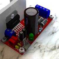
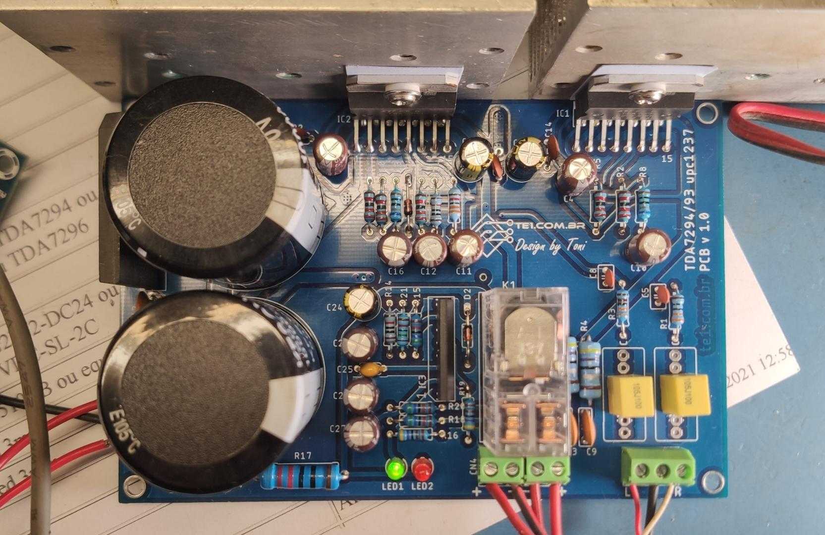
Printed circuit board (PCB) suggestion to mount the TDA7294 amplifier.


Part list to mount the dynamic TDA7294 amplifier.
Last update: 01/09/2021 10:48
| Part | Value | Description | Quantity |
| Capacitors | |||
| C1, C15, C24 | 100µF/50V | Electrolytic capacitor | 3 |
| C2, C9, C13, C14 | 100nF | Ceramic capacitor | 4 |
| C3, C6 | 470nF a 4.7uF/100V | Film Capacitor | 2 |
| C4, C7, C10, C11, C12 | 22µF/50V | Electrolytic capacitor | 5 |
| C5, C8 | 220p | Ceramic capacitor | 2 |
| C16, C20, C26, C27 | 47µF/50V | Electrolytic capacitor | 4 |
| C17, C19, C22, C23 | 100n/100V | Film Capacitor | 4 |
| C18, C21 | 4.700uF a 10.000uF /50V | Electrolytic capacitor | 2 |
| C25 | 22n | Ceramic capacitor | 1 |
| Miscellaneous | |||
| CN1 | IN | Terminal block 2 pin 5.08 mm | 1 |
| CN2 | AC | Terminal block 3 pin 5.08 mm | 1 |
| CN3 | OUT1 | Terminal block 2 pin 5.08 mm | 1 |
| CN4 | OUT2 | Terminal block 2 pin 5.08 mm | 1 |
| Semiconductors | |||
| D1, D2 | 1N4448 | Diode | 2 |
| D3, D4 | 1N4004 | Diode 1A 400V | 2 |
| IC1, IC2 | TDA7293 or TDA7294, or TDA7295 or TDA7296 | Integrated circuit Audio amplifier. | 2 |
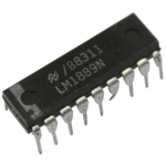
| IC3 | UPC1237 | CI protector for amplifier | 1 |
| K1 | Omron G2R-2-DC24 or Songle SMI-24VDC-SL-2C | Relay 24V | 1 |
| B1 | GBJ2510 or equivalent | 25A 1000V Rectifier Bridge | 1 |
| LED1 | Led 3 mm | led red | 1 |
| LED2 | Led 3 mm | Green led | 1 |
| Resistors 1/4W 5% | |||
| R1, R3 | 390 | Orange, white, brown, gold | 2 |
| R2, R5, R6, R7, R10 | 22K | Red, red, orange, gold | 5 |
| R4, R9 | 4.7 Ohms /1W | Yellow, violet, gold, gold | 2 |
| R8, R13 | 680 Ohms | Blue, gray, brown, gold | 2 |
| R11, R14 | 10K | Brown, black, orange, gold | 2 |
| R12 | 33K | Orange, orange, orange, gold | 1 |
| R15, R18, R20 | 56k | Green, blue, orange, gold | 3 |
| R16, R19 | 4.7K | Yellow, violet, red, gold | 2 |
| R17 | 100 Ohms /2W (see text) | Red, red, brown, gold | 1 |
| R21 | 15K | Brown, green, orange, gold | 1 |
| Weld, wires, PCB, box, transformer, heat sink for integrated, thermal paste, bushing, screws, etc. | |||
Download files from this circuit TDA7294 amplifier, PCB to print in PNG, PS, PDF formats, plus Gerber files for you to order your PCB.
Datasheet of the components used in circuit TDA7294 amplifier.
- PDF Datasheet PDF TDA7293 — STMicroelectronics
- PDF Datasheet PDF TDA7294 — STMicroelectronics
- PDF Datasheet TDA7295 — STMicroelectronics
- PDF Datasheet PDF TDA7296 — STMicroelectronics
- PDF Datasheet PDF UPC1237 — UTC (Unisonic)
- PDF Datasheet µPC1237 — NEC
- PDF Datasheet GBJ2510 — Diodes incorporated
- PDF Datasheet G2R-2-DC24 — Omron
- PDF Datasheet SMI-24VDC-SL-2C — Songle