
Table of Contents
Leach amp power amplifier 700W 2SC5200 2SA1943. Here’s a Leach Amplifier based on 2SC5200 and 2SA1943 output power transistors that can provide up to 700W of power.
About Leach amplifier
A Leach amplifier is a type of audio amplifier design that was popularized by Marshall Leach, a professor at Georgia Institute of Technology. This amplifier design is known for its high power output and low distortion, making it a favorite among audiophiles and sound engineers. The Leach amplifier typically uses a complementary symmetry output stage, which allows it to deliver high-quality sound reproduction across a wide range of frequencies. Additionally, the design of the Leach amplifier is relatively simple and straightforward, making it accessible for DIY enthusiasts looking to build their own high-performance audio equipment. Overall, the Leach amplifier is a well-regarded choice for those seeking powerful, clean, and accurate audio amplification.

Schematic Leach amp power amplifier 700W 2SC5200 2SA1943

Technical parameters:
- Output power: 680W/2R, 450W/4R, 260W/8R
- Minimum permissible load: 2R
- Amplification Class: AB
- Bandwidth: 10 – 180.000Hz/-3dB
- THD + N (Total Harmonic Distortion + Noise: at 4 ohms = <0.05% from 20Hz to 1kHz, linearly increasing to 0.1% at 20kHz
- IMD (Intermodulation Distortion): at 8 Ohms <0.05%
- Damping Factor: 400 at 50Hz at 8W, allowing low distortion and better speaker performance (especially in the bass range), in the range of 20 to 400Hz
- Use of ultra-fast transistors
- Input Impedance: 10K unbalanced
- Signal/Noise Ratio: >90dB
- Power Supply Voltage: Symmetrical 63 Volts x 12 Amperes Max 80 Volts
- Maximum allowable supply voltage: max. +/-80V
- Recommended Transformer 50+50x12A
- Amplifier protection: 2x 15A/F
- Delayed connection: approx. 1.5s
- Input sensitivity for maximum excitation: 1.1V
- slew rate: 35V/us
- Requires reinforcement in the heatsink and forced ventilation (Cooler).
Test
First, it is necessary to test the power source. We will leave fuses F2-F5 removed and check the connection of the rectifier and the polarity of the capacitors for safety. Any error could be fatal. If everything is in order, there should be a voltage of around 65V on the capacitors of both branches. The exact voltage depends on the transformer used and the voltage in the network. After disconnection, the voltage on the capacitors will hold for a long time. We can discharge them through a resistor of about 100R 2W. It may happen that when turned on, fuse F1 burns even though everything is in order. In my case, the charging current after switching on is so high that I had to install an NTC thermistor in series on the primary side of the transformer, which I took from an old PC power supply, where it served the same function. It would be better to use a “soft start” circuit, which consists of a resistor in series on the primary side of the transformer, which is shorted by a delay circuit through a relay after a few seconds. However, I have not found a circuit that I like.
If the power source is working correctly, we can proceed to test the amplifier. Trimr P1 is set to the extreme position with maximum resistance. We install 100R 1/4W resistors in the fuse holders for one channel. With the output and input disconnected, we turn on the amplifier. We should measure a maximum of 2.5V on the 100R resistor, which corresponds to a current of 25mA. If everything is okay, we wait for the power source to discharge after turning off and replace the resistors with fuses. We can start with smaller ones. I had two wires swapped to the power transistors on one channel, so the resistors started smoking and smelling bad. It really pays off to double-check everything, but mistakes can still happen.
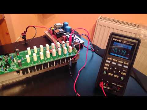
Now we need to set the quiescent current. Instead of fuse F2, we will put an ammeter and rotate trimmer P1 until we set the current to 100mA. As the amplifier heats up, the current changes. We adjust the current value until it stabilizes, which may be about 15 minutes. We repeat the same process for the second channel.
With the input disconnected, we can also measure the DC offset at the output and see how carefully we matched the components. In my case, I measured 19mV on the left and 22mV on the right channel.
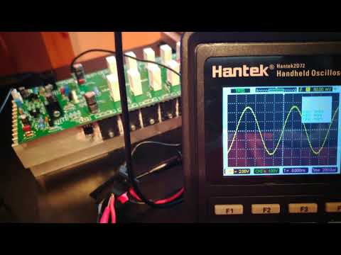
It is now possible to proceed to the sharp tests and connect the speakers and signal source. I tested it by connecting the amplifier input directly to the sound card output. It is necessary to lower the volume and carefully add, because the amplifier is powerful enough to destroy a smaller speaker.
BOM Leach amp power amplifier 700W 2SC5200 2SA1943
| Parts | Value | Description | Quantity |
|---|---|---|---|
| Capacitors | |||
| C1 | 1uF | Film capacitor | 1 |
| C2 | 390pF | Ceramic capacitor | 1 |
| C4,C3,C21,C12,C23,C9,C20,C22 | 100nF/100V | Ceramic capacitor | 8 |
| C5,C6,C7,C8,C18,C19,C25,C26 | 100uF/100V | Electrolytic capacitor | 8 |
| C7,C8 | 100uF/25V | Electrolytic capacitor | 8 |
| C10,C11,C16 | 10pF | Ceramic capacitor | 3 |
| C13 | 180pF | Ceramic capacitor | 1 |
| C17 | 47pF | Ceramic capacitor | 1 |
| C24 | 100nF | Film capacitor | 1 |
| C27,C28,C15,C14 | 47n | Film capacitor | 4 |
| Resistors | |||
| R1,R30 | 22K | 1/4W resistor | 2 |
| R2 | 2.2K | 1/4W resistor | 1 |
| R3,R4,R5,R6,R7,R8,R9,R10 | 300 | 1/4W resistor | 8 |
| R11,R12,R24,R25 | 12K | 1/4W resistor | 4 |
| R38,R41,R42,R45,R46,R49,R50,R53, R54,R57,R58,R61,R62,R65,R66,R69 |
10 | 1/2W resistor | 17 |
| R14,R15,R23 | 1.2K | 1/4W resistor | 3 |
| R16,R17 | 2.2K | 2W resistor | 2 |
| R18 | 620 | 1/4W resistor | 1 |
| R19,R20 | 390 | 1/4W resistor | 2 |
| R21,R22 | 33 | 1/4W resistor | 2 |
| R26 | 6.2K | 1/4W resistor | 1 |
| R27 | 2K | Trimpot 3296W | 1 |
| R28,R29 | 5.6K | 1/4W resistor | 2 |
| R31,R32 | 330 | 1/4W resistor | 2 |
| R33 | 220 | 2W resistor | 1 |
| R34,R35 | 100 | 1/4W resistor | 2 |
| R36,R37 | 82 | 1/4W resistor | 2 |
| R40,R43,R44,R47,R48,R51,R52,R55,R56, R59,R60,R63,R64,R67,R68,R39 |
0.5 | Cement Resistor 5W | 16 |
| R71,R72 | 22 | 2W resistor | 2 |
| R73,R74 | 270 | 1/4W resistor | 2 |
| Semiconductors | |||
| D1,D2,D3,D4 | BZX85B20V | 20V DO-41 Zener Diode | 4 |
| D11,D12,D8,D7,D6,D5 | 1N4148 | DO-35 Switching Diode | 6 |
| D9,D10 | 1n4004 | DO-27 diode | 2 |
| Q1,Q2,Q5,Q7,Q10 | BC546 | NPN TO-92-3 Bipolar transistor | 5 |
| Q3,Q4,Q6,Q8,Q11 | BC556 | PNP TO-92-3 Bipolar transistor | 5 |
| Q13 | MJE340 | NPN SOT-32-3 Bipolar transistor | 1 |
| Q14 | MJE15032 | NPN TO-220 Bipolar transistor | 1 |
| Q15 | MJE15033 | PNP TO-220 Bipolar transistor | 1 |
| Q16,Q19,Q20,Q22,Q24,Q27,Q29,Q31,Q32 | 2SA1943 | PNP TO-3PL Bipolar transistor | 9 |
| Q17,Q18,Q21,Q23,Q25,Q26,Q28,Q30,Q33 | 2SC5200 | NPN TO-3PL Bipolar transistor | 9 |
| Q34 | BD139 | NPN TO-126 Bipolar transistor | 1 |
| Q35 | MJE350 | PNP SOT-32-3 Bipolar transistor | 1 |
| Miscellaneous | |||
| F1,F3 | 5×20 BLX-Atype Fuse holder XC-7 | Fuseholder + 15A fuse | 2 |
| IN | GND | HDR-2X1/2.54 | 1 |
| LR1 | 4uH + 10 Ohm 3W | ZOBEL NETWORK COIL | 1 |
| U1 | +80V | Quick connect terminal | 1 |
| U2 | -80V | Quick connect terminal | 1 |
| U3 | OUT | Quick connect terminal | 1 |
| U4,U5 | GND | Quick connect terminal | 2 |
| U6,U7 | Heatsink to220 01 | HEATSINK | 2
|
Download files, links, and notes

- Download PCB in Gerber + BOM + Centroid file + PDF
- Mirror
- BUY transistor amplifier board
- PDF datasheet 2SA1943
- PDF datasheet 2SC5200
- PDF datasheet BD139
- PDF datasheet MJE350
- PDF datasheet MJE340
- PDF datasheet BC556
- PDF datasheet BC546
- PDF datasheet 1n4004
- PDF datasheet 1N4148
- PDF datasheet BZX85B20V


