Table of Contents
SI4735 all band radio receiver mini, LW MW FM SW Air band This project is aimed at amateur radio enthusiasts and anyone interested in building a full band (including AM, FM, SSB) radio receiver based on the core chip SI4735. The frequency range for AM and SSB modes is 150kHz to 30MHz, and for FM mode is 64 to 108MHz.
This project consists of two PCBs, the main board and the expansion board. The main board includes all basic functions, such as full band radio signal reception, processing and playback, and function key operation; the expansion board is used based on the main board, and after connecting to the main board, it can achieve: time display and clock synchronization, temperature and humidity display, and power supply from batteries.
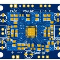
Schematic SI4735 all band radio receiver mini main board

Schematic SI4735 all band radio receiver mini expansion board v2

Components SI4735 all band radio receiver mini
- TC8002D, audio amplifier chip
- LCD screen uses 1.47 inch 12-pin soldering type
- WS2812B-B 5050 colorful LED, for decoration
- Crystal oscillator uses 32768 active crystal oscillator
- The headphone jack is PJ-320B patch socket
- The antenna socket is SMA socket, corresponding antennas with SMA interface can be purchased
- Supports AM signal receiving magnetic bar coil — SI4735-D60-GU in SSOP-24 package
- ESP32-S3-WROOM-1U-N16R8
- Clock chip RX8025T-UC, temporarily set the time by pressing buttons and using the encoder.
- To display the time, press the bottom left button. For time setting, press and hold the bottom left button, the corresponding numbers will flash, use the encoder to set the time.
- Temperature and humidity sensor SHT30, if not needed, do not solder it, it will not display temperature and humidity, the program can still work normally.
- Charging management chip Enjie core IP5306, charging control chip, single click to turn on, double click to turn off, and added a self-locking switch, so you can also turn off when charging.

Project functions
- Main interface functions
- Volume adjustment function: Short press the volume control button, rotate the encoder to adjust the audio size of the radio;
- Modulation mode selection: Short press the modulation mode selection button, rotate the encoder to select the wireless radio signal under AM\\FM\\USB\\LSB 4 modulation modes, press the encoder down to confirm the current selection;
- Manual tuning function: Short press the manual tuning button, rotate the encoder to manually adjust the frequency of the received wireless radio signal in 0.1Mhz units in both forward and reverse directions;
- Fast lock target band function: Due to the large range of radio signal bands covered by the full-band radio, the function of quickly locking a certain band is needed to reduce the workload of manual tuning; Short press the fast band selection button, rotate the encoder to quickly position the receiving band to 20M\\40M\\80M and other bands, press the encoder down to confirm the current selection;
Expansion board functions.
Expansion modules include power management, clock display and time setting, and temperature and humidity detection functions. Long press the bottom left corner button on the main interface to display the expansion interface.
Time setting function: Short press the bottom left corner function key to switch the time setting object (hour, minute, second, year, month, day), and rotate the encoder to set the time.
Introduction to motherboard design and functions:


Software Description
Based on the Arduino IDE framework, the core program logic is as follows:
[Initialization]: Initialize devices and functions, including I2C/display/SI4735/keys/encoder/power amplifier;
[Main loop]:
1. Read encoder and keys;
2. Read SI4735 status;
3. Set SI4735 (frequency, volume, etc.);
4. Interface drawing and display;
Shell design


The shell mainly includes four parts: front panel, front shell, back shell, back panel.
The front panel is made of PET material, with adhesive on the back for easy sticking, and the back panel is made of transparent acrylic. The front and back shells are made of resin material and 3D printed, with the front shell painted in Pantone color 1795C. The shell customization was completed by Jialichuang panel customization and Jialichuang 3D printing.

BOM Main Board SI4735 all band radio receiver mini
| Part | Value | Description | Quantity |
| Resistors | |||
| R1,R5 | 10Ω (100) | R0603 – SMD resistor | 2 |
| R2,R6,R13,R14,R17,R18,R19,R20,R21,R24 | 10kΩ (103) | R0603 – SMD resistor | 10 |
| R3,R4,R9,R15,R16 | 4.7k (472)) | R0603 – SMD resistor | 5 |
| R7 | 0Ω (0) | R0603 – SMD resistor | 1 |
| R8 | 1kΩ (102) | R0603 – SMD resistor | 1 |
| R10 | 620Ω (621) | R0603 – SMD resistor | 1 |
| R11,R12 | 2kΩ (203) | R0603 – SMD resistor | 2 |
| R22,R23 | 47kΩ (473) | R0603 – SMD resistor | 2 |
| RN1,RN2 | 4.7kΩ (4732) | 0603×4 Resistor Networks & Arrays | 2 |
| Capacitors | |||
| C1,C3,C5,C6,C9,C10,C14,C15,C16 | 100nF | C0603 – SMD ceramic capacitor | 9 |
| C2,C4 | 10uF | C0603 – SMD ceramic capacitor | 2 |
| C7,C8 | 100pF | C0603 – SMD ceramic capacitor | 2 |
| C11,C12,C24,C25 | 4.7uF | C0603 – SMD ceramic capacitor | 4 |
| C13 | 22nF | C0603 – SMD ceramic capacitor | 1 |
| C17 | 470nF | C0603 – SMD ceramic capacitor | 1 |
| C18,C19 | 22uF | C0603 – SMD ceramic capacitor | 2 |
| C20,C23 | 2.2uF | C0603 – SMD ceramic capacitor | 2 |
| C21,C22 | 22uF/16v | Tantalum Capacitor CASE-A-3216 | 2 |
| Semiconductors | |||
| D1 | BAV99 | SOT-23 Switching Diode | 1 |
| LED | WS2812B-B/W | SMD5050 RGB LEDs (Built-in IC) | 1 |
| LED6 | KT-0603R | Red LED 0603 | 1 |
| U1 | AMS1117-3.3 | 1A Fixed 3.3V PositiveSOT-223-3 Linear Voltage Regulators (LDO) | 1 |
| U2 | ESP32-S3 | ESP32-S3-WROOM-1U-N16R8 | 1 |
| U3 | SI4735-D60-GU | SSOP-24 150mil | 1 |
| U6,U7 | TC8002D | 3Wx1@3 Ω SOIC-8 Audio Power OpAmps | 2 |
| Q1 | AP2300 | SOT-23 N-Channel MOSFET — 20V 5.2A | 1 |
| Miscellaneous | |||
| IO,PWR | HDGC2001WV-4P | Connector 4 pin — 2 mm | 2 |
| L1 | 270nH | L0603-RD | 1 |
| LCD | 1.47 inch IPS172*320 | 1.47LCD-IPS-172×320-front | 1 |
| AMI | HDGC2001WV-2P | Connector 2 pin — 2 mm | 1 |
| ANT | BWSMA-KE-P001 | SMA Board Edge Connectors | 1 |
| LEFT,RIGHT | 1.25-2P | 1×2P 1.25 mm SMD connector | 2 |
| PROG | HC-0.8-6PWT | 1×6P 1 Tin 0.8 mm Right Angle SMD connector | 1 |
| AUDIO | PJ-320B | 3.5 mm headphone jack SMD | 1 |
| SW0 | EC11 Horizontal Encoder | EC11 Horizontal Encoder | 1 |
| SW1,SW2,SW3,SW4,SW5,SW6,SW7,SW8 | Tactile Switches | SMD Tactile Switches F 4P-L6.0-W6.0-P4.50-LS9.0 | 8 |
| RESET | 1188E1W3QR4 | Tactile Switches 3.5×7.8 mm right angle SMD | 1 |
| USB | KH-TYPE-C-16P | 3A 1 Surface Mount,Right Angle 16P Female | 1 |
| X1 | 32.768KHz | SMD3225-4P Oscillators | 1 |
BOM extension Board SI4735 all-band radio receiver mini
| Part | Value | Description | Quantity |
| Resistors | |||
| R1 | 2Ω (2R0) | R0603 – SMD resistor | 1 |
| R2,R3,R5,R6,R7,R9 | 10kΩ (103) | R0603 – SMD resistor | 6 |
| R4 | 0.5Ω (0R5) | R0603 – SMD resistor | 1 |
| R8 | 100Ω (101) | R0603 – SMD resistor | 1 |
| R10 | 2kΩ (203) | R0603 – SMD resistor | 1 |
| R11 | 47Ω (47) | R0603 – SMD resistor | 1 |
| R12 | 1MΩ (106) | R0603 – SMD resistor | 1 |
| Capacitors | |||
| C1,C2 | 10uF | C0603 – SMD ceramic capacitor | 2 |
| C3,C4,C5,C6,C8 | 22uF | C0603 – SMD ceramic capacitor | 5 |
| C7, C9, C10, C18 | 100nF | C0603 – SMD ceramic capacitor | 2 |
| C11,C12,C19,C20 | 100pF | C0603 – SMD ceramic capacitor | 6 |
| C13 | 10nF | C0603 – SMD ceramic capacitor | 1 |
| C14,C16 | 27pF | C0603 – SMD ceramic capacitor | 2 |
| C15 | 47pF | C0603 – SMD ceramic capacitor | 1 |
| C17 | 12pF | C0603 – SMD ceramic capacitor | 1 |
| Semiconductors | |||
| LED1 | PWR | Red 0603 LED | 1 |
| LED2 | 25 | Red 0603 LED | 1 |
| LED3 | 50 | Red 0603 LED | 1 |
| LED4 | 75 | Red 0603 LED | 1 |
| LED5 | 100 | Red 0603 LED | 1 |
| U1 | IP5306 | ESOP-8 Battery Management | 1 |
| U2 | SHT30-DIS-B10KS | Sensor humid/temp 5v i2c 2% SMD | 1 |
| U3 | RX8025T-UC | I2C SOP-14-208mil Real-Time Clock | 1 |
| U4 | SA602AD/01,118 | 17dB 5dB SOP-8-150mil RF Mixer | 1 |
| U5 | BGA2818,115 | SOT-363-6 RF Amplifier | 1 |
| U6 | 10.7 MHz ceramic filter | SIP-3_L5.4-W2.1-P2.54-L | 1 |
| U7 | SI5351A-B11307-GTR | 200MHz MSOP-10 Clock Generator | 1 |
| Miscellaneous | |||
| CN1,CN2 | HDGC2001WV-4P | Connector 4Pin 2 mm | 2 |
| CN3 | BAT | Connector 2Pin 2 mm | 1 |
| KEY1 | Self-locking switch | SW-TH_6P-L5.8-W5.8-P2.00-LS4.5-TR | 1 |
| L1 | 1uH | SMD,4.8×4.2 mm Power Inductor | 1 |
| L2,L3 | 82nH | L0603 | 2 |
| L4 | 10uH | L0806 | 1 |
| SW1 | KEY PWR | SMT button 5H 6×6 | 1 |
| X1 | 25MHz | SMD3225-4P Crystal | 1 |
Download files and info
Download PCB in Gerber + esp32 Firmware
Files you will use
- FirmwareESP32S3_Radio_v0515.zip — Firmware for ESP32
- Gerber_Main_PCB_2023-05-20.zip — Gerber for Main PCB
- Gerber_EB_PCB_V2_2023-05-28.zip — Gerber for extension PCB V2
- Radio-housing design.zip — 3D case
Buy components for this project
- Buy Display 1.47LCD-IPS-172*320
- Buy SI4735 IC SI4735-D60-GU SSOP-24 si4735 4735d60gu
- Buy ESP32-S3-WROOM-1U-N16R8