Table of Contents
Lm5122 module 20v 200W synchronous boost controller. Upgrade your power supply with the LM5122 module, a high-performance synchronous boost controller that offers up to 200W of power output. With a wide input voltage range and high efficiency design, this IC is perfect for demanding applications. Don’t settle for less, optimize your power supply with the LM5122 today!
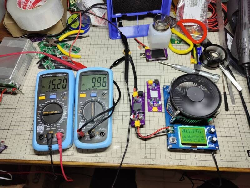
Characteristics Lm5122 module 20v 200W synchronous boost controller diy
- Input : 11-19V with XT-30+DC_044 input slot
- Output: voltage: 20.2V
- Output current capability: up to 10A
- Current limit on input side
- Max Power: 200W
Generally input current should not exceed 15A design efficiency 96% inductor can be flexibly replaced according to your actual scenario, it is recommended to adjust between 3.3-10uh.
Schematic Lm5122 module 20v 200W synchronous boost controller diy

About IC LM5122
The IC LM5122 is a high-performance, dual-channel synchronous buck controller that is designed for high efficiency power supplies. It features a wide input voltage range, up to 75V, making it suitable for a variety of applications. The LM5122 also offers a programmable switching frequency, adjustable current limit, and a voltage feed-forward function for improved transient response. With integrated protection features such as overcurrent protection, thermal shutdown, and undervoltage lockout, the LM5122 provides a reliable and flexible solution for power supply designs. Overall, the LM5122 is a versatile and efficient IC that is ideal for demanding power supply applications.
The LM5122 is a multiphase capable synchronous boost controller intended for high-efficiency synchronous boost regulator applications. The control method is based upon peak-current-mode control.
Current-mode control provides inherent line feedforward, cycle-by-cycle current limiting, and ease of loop compensation. The switching frequency is programmable up to1 MHz. Higher efficiency is achieved by two robust N-channel MOSFET gate drivers with adaptive dead-time control.
A user-selectable diode-emulation mode also enables discontinuous-mode operation for improved efficiency at light load conditions.
An internal charge pump allows 100% duty cycle for high-side synchronous switch (bypass operation).
A180° phase shifted clock output enables easy multiphase interleaved configuration. Additional features include thermal shutdown, frequency synchronization, hiccup-mode current limit, and adjustable line under voltage lockout.

BOM module 20v 200W synchronous boost controller diy
| Value | PART | Description | Quantity |
| Resistors | |||
| 3K | RB | R0402 — SMD resistor | 1 |
| 36.5K | RCO | R0402 — SMD resistor | 1 |
| 7.15K | RENB | R0402 — SMD resistor | 1 |
| 49.9 | RENT | R0402 — SMD resistor | 1 |
| 44.2K | RFS | R0402 — SMD resistor | 1 |
| 205K | RSL | R0402 — SMD resistor | 1 |
| 47.5K | RT | R0402 — SMD resistor | 1 |
| Capacitors | |||
| 22uF | CO6,CI2,CI3,CO3,CO4,CO5 | 1206 — SMD capacitor | 6 |
| 10uF | CVC | C0603 — SMD capacitor | 1 |
| 1uF | CVI1 | C0603 — SMD capacitor | 1 |
| 150nF | CBS | C0603 — SMD capacitor | 1 |
| 180pF | CCO1 | C0402 — SMD capacitor | 1 |
| 10nF | CCO2 | C0402 — SMD capacitor | 1 |
| 470nF | CRE | C0402 — SMD capacitor | 1 |
| 33nF | CSS | C0402 — SMD capacitor | 1 |
| 470uF | CI1,CO1,CO2 | 10×16 Solid Capacitors | 3 |
| Semiconductors | |||
| LM5122MHX/NOPB | U1 | Buck-boost type 4.5V~65V HTSSOP-20-EP DC-DC Converters | 1 |
| CSD17305Q5A | QB | 30-V, N channel NexFET | 1 |
| CSD17573Q5B | QT | 30-V, N channel NexFET | 1 |
| SS24FL | DBS | SOD-123 — Schottky Barrier Diodes | 1 |
| Miscellaneous | |||
| DC-044B-3A-2.0 | DC2 | DC Power Receptacle | 1 |
| 4.7uH | L1 | 17A 10uH | 1 |
| XT30PW-M | XT-IN, XT-OUT | Aircraft plug horizontal | 2 |
| 0.002R | RSS | R2512 — 2W 2 mΩ Surface Mount Current Sensing Resistors Shunt | 1 |
Download files, links, and notes

Download PCB in Gerber and PDF
- Buy LM5122 ic
- buy lm5122 MODULE
- LM5122 Wide-Input Synchronous Boost Controller With Multiple Phase Capability datasheet (Rev. H)
- How to add overvoltage protection to a synchronous boost controller
- Improve DC/DC Regulator EMI for Free with Optimized Power Stage Layout
- Designing the front-end DC/DC conversion stage to withstand automotive transient
- PMLK Boost Experiment Book (Rev. A)
- Under the Hood of a Multiphase Synchronous Rectified Boost Converter
- Under the Hood of a Multiphase Synchronous Rectified Boost Converter (PPT)
- Power Tips: Synchronize your SEPIC
- How to design boost, SEPIC or flyback regulators with wide VIN power ICs
- Automated Frequency Response Analyzer
- Wide VIN power management ICs simplify white paper (Rev. A)
- LM5122EVM-1PH User’s Guide
- LM5122EVM-2PH User’s Guide
Source: https://oshwhub.com/LoveTombSeries/LoveTomb584


