Table of Contents
Circuit FM band stop filter (notch filter). It is usually used in the front end of satellite receivers, SDR software radio receivers. Strong FM signals may block the LNA and affect the quality of the desired signal reception, so an FM band stop filter is needed to filter out local strong FM signals.
Schematic Circuit FM band stop filter (notch filter)
 1 Best Fm Transmitter, Circuits, Filter Cad Drawing, Filters, Fm Transmitter, Fm Transmitter Circuit, Fm Transmitter Circuit Diagram, Fm Transmitter Circuit Project, Rf, Transmitters")
What is an elliptic filter?
An elliptic filter (Elliptic filter), also known as a Cauer filter, is a type of filter with ripples in both the pass-band and stop-band. Compared to other types of filters, the elliptic filter has the smallest pass-band and stop-band ripples under the same order. The ripples in the pass-band and stop-band are the same.
Characteristics of several common filters at the same order:
- Butterworth filter has the flattest pass-band and slowest stop-band descent;
- Chebyshev filter has equal ripples in the pass-band and faster stop-band descent;
- Elliptic filter has the fastest stop-band descent while having equal ripples in the pass-band;
- Bessel filter has equal ripples in the pass-band and slowest stop-band descent, with the worst frequency-selective characteristics. However, the Bessel filter has the best linear phase characteristics.
About Stop band-filter
A stop band filter is a type of electronic filter that allows certain frequencies to pass through while blocking or attenuating others. It is designed to eliminate specific frequencies or ranges of frequencies from a signal, effectively creating a “stop-band” where those frequencies are not allowed to pass. This type of filter is commonly used in audio and telecommunications systems to remove unwanted noise or interference, resulting in a cleaner and more precise signal. Stop band filters can be implemented using various techniques, such as passive components like resistors, capacitors, and inductors, or active components like operational amplifiers. Overall, stop band filters play a crucial role in signal processing and communication systems by improving signal quality and reducing interference.
Simulate the filter using simulation software:
 2 Best Fm Transmitter, Circuits, Filter Cad Drawing, Filters, Fm Transmitter, Fm Transmitter Circuit, Fm Transmitter Circuit Diagram, Fm Transmitter Circuit Project, Rf, Transmitters")
Obtain simulation results:
It can be seen that this filter can effectively attenuate the FM band to a large extent, achieving the design purpose.
 3 Best Fm Transmitter, Circuits, Filter Cad Drawing, Filters, Fm Transmitter, Fm Transmitter Circuit, Fm Transmitter Circuit Diagram, Fm Transmitter Circuit Project, Rf, Transmitters")
Calculate impedance and draw PCB:
Use the CPWG model for calculation. So please do not change the PCB copper settings, line width, board thickness (1.2 mm), and component placement randomly unless you know how to handle impedance.
 4 Best Fm Transmitter, Circuits, Filter Cad Drawing, Filters, Fm Transmitter, Fm Transmitter Circuit, Fm Transmitter Circuit Diagram, Fm Transmitter Circuit Project, Rf, Transmitters")
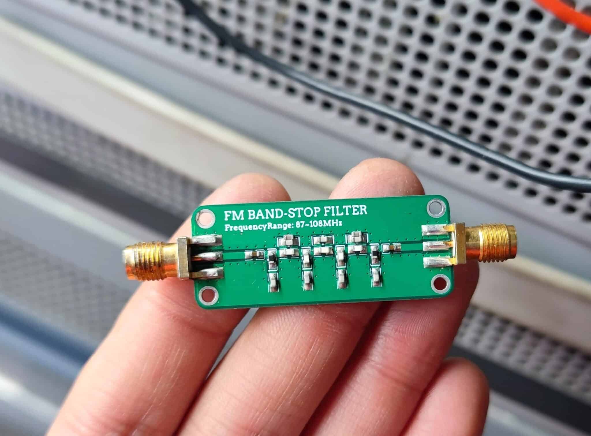
Produce the physical PCB and solder:
 5 Best Fm Transmitter, Circuits, Filter Cad Drawing, Filters, Fm Transmitter, Fm Transmitter Circuit, Fm Transmitter Circuit Diagram, Fm Transmitter Circuit Project, Rf, Transmitters")
Connect the soldered filter module to a vector network analyzer for testing and evaluation:
Here we measure the S21 parameters of the filter, connect the input of the filter to port 1 of the network, connect the output to port 2, and start the measurement.
 6 Best Fm Transmitter, Circuits, Filter Cad Drawing, Filters, Fm Transmitter, Fm Transmitter Circuit, Fm Transmitter Circuit Diagram, Fm Transmitter Circuit Project, Rf, Transmitters")
Observing the S21 parameters, the performance of this filter is good.
Some may ask why there is a difference between the insertion loss in simulation and actual testing, with insertion loss of a few dB in actual testing instead of the 0.x dB in simulation, and a slight change in the stop-band frequency. Obviously, simulation and reality cannot be completely consistent. Simulation uses idealized models, while reality is subject to component parameter errors, materials, board effects, etc., which is a normal phenomenon.
From the S21 parameters, it can be seen that the performance of this filter is already very good.
 7 Best Fm Transmitter, Circuits, Filter Cad Drawing, Filters, Fm Transmitter, Fm Transmitter Circuit, Fm Transmitter Circuit Diagram, Fm Transmitter Circuit Project, Rf, Transmitters")
Here is a test chart of the S21 parameters for the 9KHz~4GHz full range. The higher the frequency, the greater the insertion loss, which is a normal phenomenon caused by the components themselves.
 8 Best Fm Transmitter, Circuits, Filter Cad Drawing, Filters, Fm Transmitter, Fm Transmitter Circuit, Fm Transmitter Circuit Diagram, Fm Transmitter Circuit Project, Rf, Transmitters")
BOM Circuit FM band stop filter (notch filter)
| Value | Part | Description | Quantity |
| SMA | ANT2,ANT1 | RF_SMA_JB | 2 |
| Capacitors | |||
| 10pF | C21,C29 | 0603 — SMD capacitor | 2 |
| 1.8pF | C22,C23,C24,C25,C26,C27,C28 | 0603 — SMD capacitor | 7 |
| Inductors | |||
| 6.8nH | L14,L15,L16,L17,L19,L20 | 0603 — SMD inductor | 7 |
Download files, links, and notes
 9 Best Fm Transmitter, Circuits, Filter Cad Drawing, Filters, Fm Transmitter, Fm Transmitter Circuit, Fm Transmitter Circuit Diagram, Fm Transmitter Circuit Project, Rf, Transmitters")
Download PCB in Gerber and PDF
Source: https://oshwhub.com/lingmao/FM_BandStop_Filter


