
Table of Contents
KT0803L Stereo Digital FM Transmitter Circuit. Undoubtedly. Take your electronics skills to the next level with the KT0803L Stereo Digital FM Transmitter Circuit! Build your own compact stereo digital FM transmitter and broadcast your favorite music with ease. Challenge yourself with this project and impress your friends with the clear, sharp sound produced by this innovative circuit. Get your hands on the KT0803L Stereo Digital FM Transmitter Circuit today and dive into the exciting world of digital FM transmission. Let’s get building!
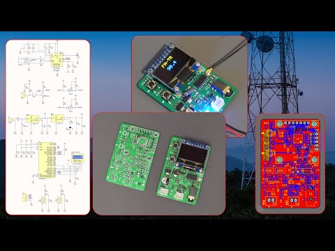
FM transmitters and receivers are popular electronic project topics, but constructing a digital FM transmitter can be a challenging task for electronics enthusiasts. This project introduces a compact stereo digital FM transmitter circuit that operates within the 87MHz to 108MHz frequency range. The frequency can be adjusted using tactile push-buttons with a 0.1MHz step size. The circuit is powered by an ATMega8 microcontroller, which communicates with a 0.96-inch SPI OLED display and the KT0803L FM transmitter chip via an I2C interface. You can connect a microphone or AUX cable directly to the board to broadcast audio from your phone or computer. Testing revealed that the circuit operates stably and produces clear, sharp sound.
Schematic and PCB design were done using Altium Designer 23, with feedback and updates shared with friends using Altium-365. The Octopart component search engine facilitated quick component information access and BOM generation. Gerber files were sent to PCBWay for high-quality board fabrication. Using this circuit promises to be an enjoyable and rewarding experience.
Specifications
- Input Voltage: 7-9VDC
- Current Consumption: 50mA
- Frequency Range: 87MHz to 108MHz
- Frequency Step Size: 0.1MHz
- AUX Input: Stereo
Schematic KT0803L Stereo Digital FM Transmitter Circuit

Power Supply
P2 is an XH connector to apply power to the board. The input voltage could be something between 7-9VDC. FB1 and C11 build a low pass filter to reduce input noises. REG2 is the TLV1117-5.0 [1] regulator to prepare the +5V voltage rail. C12 and C13 are used to stabilize the output voltage of the regulator and reduce noise. REG1 is the TLV1117-3.3 regulator [2] to prepare the +3.3V voltage rail. D1 is an LED to indicate the proper supply connection, and C10 and C14 are used to stabilize the output and reduce the noise.
Microphone Input
P1 is an XH connector to connect your electret microphone to the board. C8 is a decoupling capacitor to reduce the noise, and R6 prepares a supply rail for the microphone. C9 removes the signal DC element and Q1 [3] amplifies the weak microphone signals to be delivered to the FM transmitter chip.
Logic Level Converter
T1 and T2 are 2N7002 N-Channel Mosfets [4] that are used to convert the 5V I2C logic level from the microcontroller (U2) to the 3.3V logic level to be applied to the FM Transmitter chip (U1). R2, R3, R7, and R8 are pull-up resistors to complete the circuit.
FM Transmitter
The main component of this part is the KT0803L chip (U1) [5]. S1 is an SMD headphone jack used to connect an AUX cable to the board. This allows you to transfer sound from your mobile phone, PC, or other device to the board. C5 and C6 are used to transfer the acoustic signal to U1. C2 and C3 are decoupling capacitors, and ANT is a UFL connector that provides an interface for your telescopic antenna to the board.
Microcontroller and Display
The heart of the circuit is the ATMega8-AU microcontroller (U2) [6]. C15…C18 are decoupling capacitors to reduce the noise. R10 is a pull-up resistor for the RESET pin. LCD is the SPI 0.96-inch 128×64 OLED display, as shown in Figure 2. C19 is a decoupling capacitor for the supply pin of the LCD. SW1 and SW2 are tactile pushbuttons to increase and decrease the frequency. C20 and C21 are used to debounce the pushbuttons, and r11 and R12 are pull-up resistors. ISP prepares the necessary AVR-ISP pins to flash the MCU. Although not mandatory, you may choose to solder a pin header in place.
Code and Programming
If you just want to build the project, the same way as it is, simply download the HEX file from here [7] and program the microcontroller. Set the MCU Clock Fuse Bits to 8MHz, Internal.
If you plan to modify the code, below is the MCU code for the Arduino platform. Make sure to add this FM library [8], this SPI OLED library [9], and the MiniCore board manager library [10] to your Arduino IDE. Set the clock source on Internal, 8MHz.
#include
#include
#include "SSD1306Ascii.h"
#include "SSD1306AsciiSpi.h"

#define CS_PIN 7
#define RST_PIN 9
#define DC_PIN 8
#define Down_Key 15
#define UP_Key 14

float frequency = 87.0;
float tolerance = 0.001;

SSD1306AsciiSpi oled;
void setup() {
  fmtx_init(frequency, EUROPE);
  oled.begin(&Adafruit128x64, CS_PIN, DC_PIN, RST_PIN);
  oled.setFont(Adafruit5x7);
  pinMode(Down_Key, INPUT);
  pinMode(UP_Key, INPUT);
  oled.clear();
  oled.set2X();
  oled.println("   FM-TR   ");
  oled.setRow(3);
  oled.setCol(40);
  oled.set2X();
  fmtx_set_freq(frequency);
  oled.println(frequency, 1);
}

void loop() {
  if (digitalRead(Down_Key) == 0 && frequency > 87.0) {
    delay(130);
    frequency = frequency - 0.1;
    fmtx_set_freq(frequency);
    if (frequency < 100.0) { oled.setRow(3); oled.println(" "); oled.setRow(3); oled.setCol(40); oled.println(frequency, 1); } if ((frequency - 100.0) >= -tolerance) {
      oled.setRow(3);
      oled.println("           ");
      oled.setRow(3);
      oled.setCol(35);
      oled.println(frequency, 1);
    }
  }
  if (digitalRead(UP_Key) == 0 && frequency < 108.0) {
    delay(130);
    frequency = frequency + 0.1;
    fmtx_set_freq(frequency);
    if (frequency < 100.0) { oled.setRow(3); oled.println(" "); oled.setRow(3); oled.setCol(40); oled.println(frequency, 1); } if ((frequency - 100.0) >= -tolerance) {
      oled.setRow(3);
      oled.println("           ");
      oled.setRow(3);
      oled.setCol(35);
      oled.println(frequency, 1);
    }
  }
}
BOM KT0803L Stereo Digital FM Transmitter Circuit
| ’Designator | Qty | •Mfg Part # | Description / Value |
| ANT | 1 | U FL-R-SMT-1 (80) | 1 Inner needle IPEX Board Edge 1 25 mm |
| C1, C4 | 2 | HGC0805G0150J500NTGJ | 15pF-50V 0805 Multilayer Ceramic Capacitors |
| C2. C15, C20. C21 | 4 | 0805B105K500NT | 1uF-50V X7R ±10% 0805 Multilayer Ceramic Capacitors |
| C3, C5, C6. C7. C8. C9. C16, C17. C18, C19 | 10 | 0805B104K500NT | 100nF-50V X7R ±10% 0805 Multilayer Ceramic Capacitors |
| C10, C12 | 2 | 0805×106K250CT | 10uF-25V X7R ±10% 0805 Multilayer Ceramic Capacitors |
| C11 | 1 | RVT100UF25V67RV0011 | 100uF-25V SMD. D6.3xL7.7mm Aluminum Electrolytic Cap |
| C13, C14 | 2 | 0805B475K250NT | 4 7uF-25V X7R ±10% 0805 Multilayer Ceramic Capacitors |
| D1 | 1 | NCD0805Y1 | Yellow 0805 Light Emitting Diodes (LED) |
| FB1 | 1 | CBG321609U222T | 1206 Ferrite Beads |
| LCD | 1 | Unknown | SSD1306 128×64 0 96 SPI OLED Display Module. Yellow-Blue |
| P1, P2 | 2 | XH-2PA | Plugin, P=2.5mm Wire To Board |
| 01 | 1 | MMBT3904 | NPN SOT-23 Bipolar Transistors |
| R1, R2. R3. R6, R7. R8. R10, R11, R12 | 9 | 0805W8F4701T5E | 4 7kQ 0805 Chip Resistor |
| R4 | 1 | RMC08052 2K1%N | 2.2kQ 0805 Chip Resistor |
| R5 | 1 | SCR0805J100K | 100kQ 0805 Chip Resistor |
| R9 | 1 | AECR0805F330RK9 | 330Q 0805 Chip Resistor |
| REG1 | 1 | LD1117-3.3 | 3.3V Positive SOT-223 Linear Voltage Regulators |
| REG2 | 1 | LD1117-5.0 | 5.0V Positive SOT-223 Linear Voltage Regulators |
| S1 | 1 | C2939584 | 3.5 mm Headphone Jack SMD Audio Connectors |
| SW1, SW2 | 2 | TP10721645 | SMD SPST SMD Tactile Switches |
| T1. T2 | 2 | 2N7002 | 500mA N Channel SOT-23 MOSFET |
| U1 | 1 | KT0803L | Monolithic Digital Stereo FM Transmitter Chip |
| U2 | 1 | ATMEGA88PA-AUR | 8 KB AVR 20MHz 23 LQFP-32(7×7) Microcontroller Units |
| Y1 | 1 | X308032768KGB2SC | 32 768kHz 12.5pF ±10ppm DT-38 Crystals |

Download files, links, and notes
- Download PCB in Gerber + BOM + Centroid File
- MCU HEX File
- Arduino KT0803L Library
- SPI OLED Library
- MiniCore Board Manager
- Buy IC KT0803L
SOURCE: https://www.pcbway.com/blog/technology/Stereo_Digital_FM_Transmitter_Circuit_64d799f3.html


