Table of Contents
project of circuit potency lineal RF amplifier with BLY90 for Fm transmitter or vhf transmitter
Circuit for lineal amplifier for VHF with power source and printed circuit board, using the transistor Bly90
It is to be used as amplifier of potency of RF in the high strip of of the power source that should be capable to supply a tension of 13 volts with a current of 10 amperes. it demands right care in the assembly of the source. Terrified armored transformer, and three shocks of RF to filter the components of high frequency.
XRF1 and XRF2 are 30 you turns of wire 25 AWG in a nucleus of ferrite of 1 cm of diameter and 5 cm length. It can use one of a source at/atx bad, it is easier. XRF3 are 100 you turns of wire 25 AWG in a ferrite nucleus and 1cm of diameter for 5cm of length. Or use an usually found in the exits of sources ATX’s. something around 100µH. The capacitors C1, C2, C3, C4 should be ceramic of 600 V or more and the capacitors of 10nF are for 100v. RX cannot be of wire.
Power supply circuit for the rf lineal amplifier

About the transistor BLY90
The Transistor BLY90 was developed to work in the classes THE, B and C, with 12.5V current of 8A. For applications above 175MHZ. Below we have the diagram circuit of the amplifier using an only transistor BLY90. All capacitors should be ceramic. The resistor of 10Ω for 1 w should not be of wire, the entrance impedance and exit is of 50Ω , soon it should be linked with cable of 50Ω . It should be observed the legal restrictions as the operation of that equipment type.
Diagram circuit of the project for the rf lineal amplifier

Printed circuit board for the lineal amplifier with bly90
Below we have the drawing of the printed circuit board of the transmitter, observe that the components are mounted beside the copper and with the terminals the shortest possible, use heatsink in BLY90.

lists of material for assembly of the lineal RF potency amplifier
Power Supply
RX = 22KΩ 1W
C1,C2,C3,C4 = 100nF 600V Ceramic
C5,C6,C7,C8, =10NF 100V
C9 = 100NF
C10 = 4700µF
C11 = 2200µF
D1,D2,D3,D4 = 1N5401 or equivalent.
XRF1,XRF2 = 30 turns of wire 25 AWG in nucleus of ferrite of 1 cm diameter for 5 lengths. Optional, use a shock of RF of a computer source, those of the entrance of the net.
XRF3 = 100 turns of wire 25 AWG in a nucleus of ferrite of 1 × 5.
T1 = Transformer of 12 Volts for 10 Amperes with screening.
Several = box, plugs, cables, etc.
Amplifier of RF
Q = BLY90
R = 10 Ω 2W
C1 =15PF
C2,C3,C4,C5 = 100PF
C6 = 470NF
C7,C10,C11 = 470PF
C8 = 47PF
C9 = 56PF
C12 = 22PF
CV1,CV2 = TRIMMER 4 – 40PF
CV3,CV4 = TRIMMER 60PF MAX.
L1 = 3 turns of wire 24 AWG with diameter of 7 mm, nucleus of air.
L2 = Shock of RF of 0.22µH.
L3 = 15 turns of wire 24 AWG around a resistor of 47 Ω x 2W – The Resistor, itself, is not part of the circuit.
L4 = 3 turns of wire 24 AWG with diameter of 7 mm, nucleus of air.
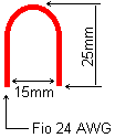
L5 = 1 turns (sees fig. below for details)
L6 = 3 turns of wire 24 AWG with diameter of 7 mm., nucleus of air.
L7 = 4 turns of wire 24 AWG with diameter of 7 mm, nucleus of air.
Several = printed circuit board, antenna, cables, heatsink, box, etc.
 Detail of L5.
That project is just for ends of didactic test, that doesn’t implicate in any responsibility of the idealization about the non operation or illegality of operation of the equipment.


Salam.please send me,rf + buffer circuit for these RF POWER with BLy 90.thank U
Muy interesante tus circuitos, vale la pena meterle mano, felicitaciones, yo estoy interesado en la fuente.
tendras la placa de circuito impreso pera la fuente?
Gracias y Saludos!
thank you very much for your wibsit please send me more Printed circuit board