Table of Contents
TDA2030 2.1 amplifier board circuit diagram subwoofer. This circuit is a complete application is 2.1 amp, two satellite speakers for TDA2030 and one for the subwoofer, the 2.1 system, widely used in commercial applications as an amplifier for computers, which may give an increased in its audio system with a stereo amplifier + bass amplifier (subwoofer).
The circuit is divided into 3 parts: power supply, stereo amplifier and bass amplifier (subwoofer).
Power supply circuit for the power circuit and the pre + low pass filter for the sub
The power supply is of the symmetrical type, it uses a transformer according to the network in your region, 110 or 220 with double secondary of 12 volts. I recommend using a fuse and a switch before the transformer. B1 is a rectifier bridge of at least 100 volts/4 A, an example that can be used is the GBU606, the filtering is up to the capacitors C8, C9, C10 and C11, the electrolytic can have values starting at 4,700µF. To power the bass filter op amp, three-terminal LM7812 and LM7912 integrated circuits are used.
Satellite speaker amplifier circuit
The right and left channels are exactly the same, let’s see how the left channel works: CNIN is the audio input connector, coupled by C2 to the volume adjustment potentiometer, it is a double potentiometer, adjusting both channels simultaneously. R3/C4 and R16/C29 help to improve the treble signal. Capacitors C6 and C31 couple the signal to IC2 and IC6 (TDA2030), after amplification the audio output is pin 4 of the integrated TDA2030. Resistors R7/R9 and R20/R22 are responsible for feedback, so by changing the value of R7 and R20 we can increase or decrease the amplifier gain. R11/C12, R24/C35 and R23/C34 form the compensation network for the speakers.
Subwoofer pre and amplifier circuit
The signal to the subwoofer comes from the left and right channels through resistors R1 and R2 being coupled by capacitor C5, is applied to amplifier 1 of the operational NE5532 IC1A, which forms a preamplifier to boost the signal by 6 times. Determined by resistors R6/R8.
The components R10, R12, C18, C17 and IC1B form a low-pass filter that in this case is calculated for 200Hz. After leaving IC1B the low frequency audio goes through potentiometer P1 that makes the volume adjustment, then forwarded to IC3 that is the bass channel amplifier, the working principle is the same as the satellite amplifiers.
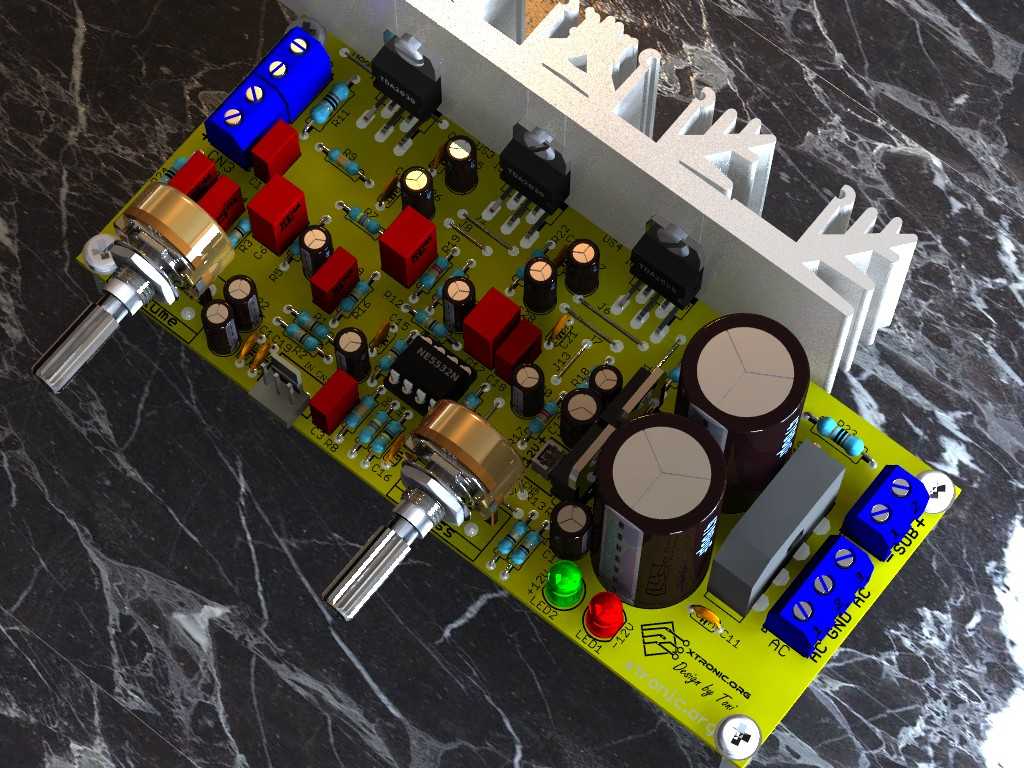
TDA2030 2.1 amplifier board circuit diagram subwoofer

PCB for TDA2030 2.1 amplifier board circuit diagram subwoofer


This is our suggested PCB for mounting the circuit, an observation is that as I did not design it for double-sided at first, we have to use some jumpers in the circuit. The circuit works even if mounted on a single-sided board. This time to try a more compact board the components are closer to each other, as well as a different assembly for several resistors in the circuit. The board is very detailed with downloadable PDFs of the board + schematic + component side and silk screen, all in high resolution.
In board version 2021 with some improvements and available Gerber file for making the PCB. However, the board is still fully compatible with home production board, but now with better component positioning and smaller dimensions. Some additional filter components have been added.
Also, included is a 12V power connector to be used for powering MP3 and Bluetooth modules.
For power supply a 12 + 12V/4A transformer can be used if used with TDA2030 or up to 17 + 17V if mounted with TDA2050 or LM1875. In this case, the working voltage of the electrolytic capacitors should be 35V. However, even with TDA2050 or LM1875, you can use a 12 + 12 V transformer.
| Table of components to be used | ||||
|---|---|---|---|---|
| IC | TDA2030 | TDA2050 | TDA2040 | LM1875 |
| Maximum power supply | 12+12 VAC | 18+18 VAC | 14+14 VAC | 18+18 VAC |
| Maximum power* | 3×18 W | 3X 35W | 3X 30W | 3x 30W |
| Working voltage of the capacitors | 25V | 35V | 35V | 35V |
It can also be combined the chips as 2X TDA2030 + 1X TDA2050 with 12+12 VAC trafo and maximum power up to 18+18+24 Watts.
Nothing prevents using any of the Cis as TDA2050 with lower voltage trafo.
The recommended heat sink is 100 x 33 x 45 or larger
It is important to insulate the body of the TDA2030 ICs from the heatsink using insulation between the metal parts. Including sleeves for the screws.

Appearance of some components used in this assembly TDA2030, NE5532, 7812, 7912

Can be used TDA2030, TDA2030A, TDA2030H, TDA2040, TDA2040V, TDA2050, TDA2050A, TDA2050L, TDA2050G, TDA2050V, Lm1875, LM1875T or equivalent
NE5532, SA5532, SE5532, NE5532A, SE5532A or equivalent
BOM to assemble amplifier TDA2030 2.1 tda2030 2.1 subwoofer circuit diagram
Last update: 08/17/2021 19:15
| Part | Value | Description | Quantity |
| Capacitors – Electrolytic 25 to 35V – Polyester and Ceramic 50 to 100V | |||
| C1, C19 | 120p (121) | Ceramic Capacitor | 2 |
| C2, C5, C7, C22, C33 | 10µF/25V | Electrolytic Capacitor | 5 |
| C3, C12, C18, C34, C35 | 100n/63V (104, 0.1u, .1, 100n) | Polyester Capacitor | 5 |
| C4, C29 | 2n2/63V (222, 0.0022, 2200p) | Polyester Capacitor | 2 |
| C6, C17, C31 | 220n a 1µF/63V (224, 0.22u, .22, 220n) | Polyester Capacitor | 3 |
| C8, C9 | 4700µF/25V | Electrolytic Capacitor | 2 |
| C10, C11, C15, C16, C20, C21, C23, C24, | 100nF ((104, 0.1u, .1, 100n) | Ceramic Capacitor | 8 |
| C13, C14 | 100µF/25V | Electrolytic Capacitor | 2 |
| C25, C26, C27, C28, C32 | 22µF/25V | Electrolytic Capacitor | 5 |
| C30 | 4.7µF/25V | Electrolytic Capacitor | 1 |
| Semiconductors | |||
| B1 | KBL608 or equivalent | Bridge rectifier | 1 |
| IC1 | NE5532 or equivalent | DIP8 dual operational amplifier | 1 |
| IC2, IC5, IC6 | TDA2030A or equivalent | Audio amplifier integrated circuit | 3 |
| IC3 | LM7812 | 3-pin voltage regulator, 12V positive | 1 |
| IC4 | LM7912 | 3-pin voltage regulator, negative -12V | 1 |
| LED1, LED2 | LED 5 mm | Red LED | 2 |
| Resistors 1/4W 5% | |||
| R1, R2, R3, R10, R12, R13, R14, R16 | 10k | Brown, Black, Orange, Gold | 8 |
| R4 | 100k | Brown, Black, Yellow, Gold | 1 |
| R5, R17, R19, R21 | 22k | Red, Red, Orange, Gold | 4 |
| R6, R7, R18, R20 | 470 | Yellow, Violet, Brown, Gold | 4 |
| R8, R9, R22 | 33k | Orange, Orange, Orange, Gold | 3 |
| R11, R23, R24 | 10 / 0,5W | Brown, Black, Red, Gold | 3 |
| R15 | 1k | Brown, Black, Red, Gold | 1 |
| Miscellaneous | |||
| CN1 | OUTL (Left channel output) | Male KK connector 2.54 mm 3-way | 1 |
| CN2 | OUTL (Left channel output) | Terminal block 2 pin 5.08 mm | 1 |
| CN3 | OUTR (Right channel output) | Terminal block 2 pin 5.08 mm | 1 |
| CN4 | SUB (Subwoofer output) | Terminal block 2 pin 5.08 mm | 1 |
| CN5 | 12V (12V DC output) | Male KK connector 2.54 mm 3-way | 1 |
| CN6 | AC (Power Transformer) | Terminal block 3 pin 5.08 mm | 1 |
| P1 | 47K (473) | Double potentiometer | 1 |
| P2 | 47k (473) | Potentiometer | 1 |
| Solder, Wires, Pci, Box, transformer, knob, screws, heat sink, insulation mica, etc | |||
*C3 is not required.
For mounting on the board or in front of the cabinet(in this case use shielded wires for connection)
You can buy PCBs or kits to assemble in sites like eBay and AliExpress, in these last ones with interesting prices… but for those who like to assemble according to their taste, hands on!
That’s it guys, this is the first version, in the next one we’ll try other more powerful integrated ones and also a bridge assembly for the bass amplifier, please leave your opinion, if there is something wrong or to be improved, let us know, that’s it for now… now it’s 1:20 a.m.!
Just a reminder that if you want the library for TDA2030 2.1 and Ne5532 for Eagle, these components are in the Linear library.
Download PCB files in PDF: TDA2030 datasheet, NE5532 datasheet, Schematic of the amplifier 2.1, PCI board, component side, Silk Screen. Just remember that whoever Libraries (library) for the TDA2030 and NE5532 for the Eagle, these components are linear in the library.
Buy diy kit TDa2030 2.1 in Aliexpress


hi Toni, i have made this pcb but subwoofer ics have continuous humming without any input and both volume at zero. if we disconnect input form bass potentiometer tda 2030 don’t have humming . i have tried each and every thing but 120hz humming is not going . even i have removed one ic from bridge pair but humming is continuous . it will be very helpful if you can tell about this issue. or share your mail id i will share photos or video so you can understand this issue.
Hello Bhupender,
https://xtronic.org/contact/
7812 an 7912 need heatsink ? or not
Hi NimnaBro
No.
Hi tony,
You are using 12v 3a power supply. But but regulating it with 7812 gives output of max 1A. So is it of to use 12v 1A power?
Hello Nandan
Regulators 7812 and 7912 are for powering operational amplifiers
hi bang toni, I am grateful from Indonesia
I want to ask you. how to do your 2.1 circuit so that the satellite RL becomes a midel sound and loud sound? and in the subwoofer, let alone what components need to be changed?
so and thank you, the answer is wait bang
. Toni,gimana caranya biar satelit RL nya biar suaranya midle dan lebih tebel apa saja yg perlu di rubah?
Hi tony , Greeting from India.
Taking reference from this circuit i have designed my own Circuit. the Only change is that i used different IC for Subwoofer Channel.
I am having a problem , the problem is that the Subwoofer channel is making Scratch / Clipping Noises while playing . I think the problem is in Low pass Filter because when i fed the Normal Signal to Subwoofer channel it Works Smoothly.
kindly help me here … Please Mention a way to personally contact you.
Hello Rajat
Please send me photos!
Can you please explain the calculation of each component and output voltage ?explain the design process of this speaker system.
हाई टोनी सर Pcb की साईज क्या हे
Hello मुकेश
15.9 x 6.7 cm; 6.28 x 2.62 inches
Ic get hot and its not working
HI Melson
Send me the photos!
hi toni, I want to ask you, if I use polyester 2A224J polyester, what will happen
Hi Hari
Is Ok!
Hi Toni…! How many watts speakers and sub woofer will be best to use for the above circuit?
Hello KR
Speaker: 4 or 8 ohms 20~50W
Subwoofer: 4 or 8 ohms 50W.
Hello Mr.Toni I cannot able to download the PDF file. Kindly send me a copy to my mail ID: [email protected]. How much Watts speakers and woofer must be used for this circuit? Which online website that I can able to buy all these components?
This site is one of the best I have found.
Hello Agen
Thanks your feedback!
I utilize the design however doesnt work for me.when I turned on d circuit a boisterous commotion will turn out and the 3 tda2030 were so hot.what should I do?pls help me!
Hello Electrical design
Please send me the photos!
What are the voltages of 100nf, 220nf and 222 capacitors?
Hello Janaka
50V!
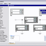
Hi !
Who knows which soft is that on top with 3D modelling pcb board ?!?
Hi Alex
Eagle 3D + PovRAy
Hi TONI hope you are fine.I want to ask two things,first one is that i have 10W woofer speaker and 6W tweeters.Can these speakers make nice sound and bass.And secondly SILK file which you have zipped has no equal layout size with that of pcb,Can you send the silk file equally in size with that of PCB.Also Can 2A 12-0-12 transformer power this circuit.Waiting for your quick reply,Thanks
Hello Muhammad
The PDF files update!
In your case use with 9V transformer.
Hi sir,
I have done this circuit and it works well.
I have been running the board over 6 months , without any problem .
With use of at least 2 to 3 amps of power supply you can obtain undistorted and noise free output .
Hello Vivek
Thanks your feedback!
Help me.whts Board size
Hello kelum
15,8x 6,3 cm
What c2 and c7 value with voltage
Hello Ashish Rajpoot
50V
Hello Mr.Toni !
Can you pls design an 2.1Ch audio amplifier using TDA7388 & NE5532 ICs ? I am newbee & want to design my own car amplifier. I already ordered these two IC from aliexpress.
Hello Atul Kumar
noted here, for future project
Please tell me substitute for NE5532N Ic.
can i use LM358 or else?
vocals and music still go in subwoofer .. its not the bass just go in subwoofer … how to solve it
Hello Halim
Add a high pass filter
what is vdd and vss, what is the power suplay?
Hello Sanooj
VDC VDD VS + VS + –> Positive supply voltage
VEE VSS V- VS- –> Negative supply voltage
I have done this circuit but there is more noise from the subwoofer. How to avoid it.plz suggest me the right solution
Comment:hai toni can i joint all Vss and Vdd together plz help me
please suggest if i have no 4 A 100V bridge rectifier. what type of diode would be used
my woofer has a problem in base sound no signal output on the base speaker help please
I have 2.1 home theater which is also known as 2030 home theater. Can anyone send me the simple wiring diagram? It has 4 ic on one side and one on the other side. I can send the pic just provide the diagram.
Sir i want to use tda 2050 ic instead of tda 2030 for more output , can i use it ? If yes please tell me transformer vol. and Amp.
Hi Toni,
I want share this 2.1 Channel
thanks
look at wesite
http://www.mediafire.com/file/j6s359vktlryh5d/DIY+2.1+Channel+Pack.zip
I want to build a circuit of ice tda 2030 to DC 12v is it possible
I Have a problem…..
For the third time my TDA2030 amp ic goes dead after 15 to 20 minutes running.
please help me
HOLA TONI, SALUDES DASE EL SALVADOR. ME HICE ESTE CIRCUITO Y EN LAS SALIDAS SOLO OBTENGO UN SONIDO “BUUUUUUUUUUUUUUUUUUUUUU” MUY FUERTE.
bro can you plz help me to add a bass and treble control for the speaker and woofer.
I m not much into electronics so plz give the ckt diagram.
i will be grateful.
plz reply me at [email protected]
Hi Toni, With the circuit for 2.1 3x18watt using TDA2030. Can TDA2050 be used in place of TDA2030 in this circuit. Thank You.
or can i use 4 Amp 400V Bridge Single Line (RS404L)
i have tda2030 4.1 home theater board, please tell me the right potentiometer for bass and volume. if possible please send me the circuit diagram my email id is [email protected]
Why my power audio board have very low volume after i put in max ??
Sorry i cant download may u send please a pdf file on my mail [email protected]
https://www.dropbox.com/s/ed6hkxbyqe6sxyy/tda2030_2.1_te1.com.br.zip?dl=1
I am souhardya I have I problem that how to input audio signal in the circuit with volume . plzz help me
Hello Souhardya
What doubt?
i build subwoofer amplifier portion of this circuit but it distorts very much with audio please help
Hello Ione
The subwoofer only plays low frequencies, the audio is not intelligible
Hi
I have built the subwoofer part of the amplifier,the audio gets more distorted while operating,is there any way to remove distortion……?
Comment:plizz describe on how to connect the ground on the ic(that is power supply.)
Hi Dennis
No ground in the IC.
hi,what is the output power
Hello , i want to use this circuit in my car . But my car battery is of 12v only . How can i operate with it
The circuit is working perfectly. Thanks
Ic 5532 gets very hot and distortion in sounds
Place a heat sink .
Any kind person who can explain the whole circuit? From the AC Transformer to the output speakers. Thanksssss. And also, does 3 x 18W means the total output power is 54W? Am I right? Where is V+ and V- is connected in the amplifier circuit? And explain that VDD and VSS. Sorry for my lot of questions. Thanks in advance! :D
I have tried to build this amplifier but it produce distorted sounds, not clear sound… I don’t know why?
I already double check all the possible error… but i found none… i followed the layout etc. everything
Is there anyone who can help fix…..
Hello Mannaseh
Please send me photos
https://www.facebook.com/te1.com.br/
cannot find a 100 v 4 amp bridge rectifier , can i use 4 Amp 800V Bridge Rectifier in place of this
i want to oprate on 12v car battery
Hello nirmal
With 2 batteries
hi
it has a noise in subwoofer output.
please help me
I need it!!!!
hi,
my name is ajay, ouer intex 2.1 multimedia home tether, use tda 2030a ic , sub sound is very low iam change the ic but sound not working properly, what well take designee, please help me
with what i had experienced, this circuit works well with max supply of 12.5-0-12.5, it can be 3-5amps.. 9-0-9 trans also works fine but with lower power output… higher than 12.5 VAC will blow the semicons.. for speakers, 4ohms are more desirable for a more powerful output…
WHAT IS THE Difference between TDA2030A AND TDA2030V. WHICH IC IS THE BEST FOR THIS APPLICATION? PLZ REPLY…
You can use both.
Thanks !!! Like…
HELLO AUTHOR!!
CAN U PLZ GUIDE ME ABOUT THE POWER SUPPLY FOR THIS CIRCUIT,,,I BLEW MY 4700uF CAP TWICE WHAT IS CAUSING THE PROBLEM AND THE REGULATORS AND HEATING UP TOO MUCH!!!
I AM TOO FRUSTRATED BCZ I HAVE SPENT A LOT ON THIS PROJECT!!!
ANY REPLY IS WELCOMED…..
if u used 3amps, 4700 cap will be ok but if you used 5 amps, then u need two 4700caps in parallel in each side of the supply
Hello!
I want to know that Can I use 12-0-12 5 A transformer in place of 12-0-12 3A Transformer ? And what are the maximum output watts of this circuit ?
Can I use 40 watt subwoofer with two satellite speakers of 10 Watt each.
Mail me at [email protected]
can we attached 19 volt & 3.4 amps in place of 12 volt & 3 amps ?
HLO every one i made it ? tell me how watt/ohm for subwoofer and how what / ohm for sattlite speaker required ? 2>>>>>>>>>>>>> if i have give 19 volt and 3amps is there any effect on circuit ? plz reply me
Yea very much possible. Make sure that it is well rectified using Diodes and two 3300uF 50V caps for smothening the 12DC
i would like to ask how to connect the transformer the one i have is a 3amp 12 volt center tap would it work
I want to know that what is the actual power supply required for this circuit…12+12mean12-0-12
Please I have been searching for a circuit like this for many days! I have a Simmetric Transformer of 3 AMP how it will work!?
Hello everyone ,
I want to make this circuit and i have added all the components to my cart.
Can anyone please tell me about the performance of the circuit ?
I also want to know the PCB size ? Which transformer and subwoofer will work well ? What to do if noise creates problems?
Please email me all the answers on…
[email protected]
with regards
Ashish
I’ve been building your 2.1 where two tda 2030 are bridged to give out more output . im feeding +9v and -9v . and I’m also getting 9vdc on da every speaker output. . help me pls. Iam using a ups transformer to power da circuit
I will try this one, but i will modification this schematic before, wait for the result !
Any connection between _ve voltage and ground..?
Dear Tony, for quick respond.
Rgrd.
Yassud
Help me!! I want to buld an subwoofer amp just give me bass i wana an
circut
The good circuit, I built it two times, and the excellent two.
whitch transformer u have use
Hi, I want to rebuild my burned out by overload Overtech SG-164 because this schematic is soo similar, but the original device uses TDA2050 and goes ok. Other things are different but not relevant. I Strongly Recomend put the amplifier in Another Box, Not into the Subwoofer! Commercials devices comes this way, and it’s like expose the components to an earthquake 9 in Richter scale, nothing can survive this, I had to resold the power condensers! But the main problem in this schem is the OverHeat! I have good disipation, putted a cooler but it wasn’t enough. The transfomer values in the Overtech: 15V x 2 ~ 1.7A (I think aren’t enough, the transformer and the whole power supply must give more current otherwise it will be overloaded, overheated and get Burned! As well said other guy up before) I’ll try to assemble it, even I don’t like to make printed circuits from PCB’s at all. Left pics of my trafo, circuit up and down burn stain. Thanks Toni for this superb job, I’m Electronics Technician from high school and I saw a schem as well as you have described this really few times. Regards from Argentina!
how can I merge tda 2030 for building woofer thanks
i made it its working but some change is need. 1. i used 470 ohm resistance in place of regulator ic.2. op amp circuit is very bad and need to change.
what is the change for op amp?
Hey guys , The circuit is good but there are a lots of noise issues in this circuit…
If any one want a complete guidance regarding this circuit then contact me on my mail id
[email protected]
i have a complete tutorial on a wide range of audio circuits.
connect alumenium plate to earthing
hi, there is so much comment on this circuit but i decide to make this amplifier.i will tell you everything about this circuit.
To those having problems with the subwoofer(bass volume) replace c16 and c22 with polyester w/ same rating… it worked for me.
I am getting heaps of noise, tryed adding a preamp amp no help. There is noise in both the left and right. The noise in the sub clears up after increasing its volume a bit. I need this to work for my major project. Which is essential for my hsc and getting into university. if anyone has any idea why its not working please email me [email protected]. please help me
I am willing to pay for your time if you can help get it working. Please help
just add filter capacitor near tda2030
hey , Do you need a proper guidance on this circuit?
i have video tutorials as well as skype support for you ..
[email protected]
Feel free to contact me
It tottaly failed for me……even with the regulators this circuit tottaly sucks!!!!One of the TDA chips even caught fire!!!
BETTER DELETE THIS CIRCUIT!!!!!
And also a lot of noise..can’t even hear any music
0 amplification!!!!!!!
I want to buy the Description of the amplifier circuit with TDA 2030. Any one can give me the contact details of delar/saler for this above circuit. My cell number is +919409176617.
hi can i use ne5532p inplace of ne5532n??
also can i use its pre-amplifier only n connect it to other power amplifier as i am unable to find tda 2030 here??
plzz reply soon
hi i made this but didnt successful.so i wanna know can i use ne5532p in place of ne5532n?
and can i use it pre-amplifier only upto bass controller??
plzz reply soon
What kind of heatsinks should I use for TDA2030 and regulators?
do we need to use logarithmic or linear pots? will 1A voltage regulators be fine or do we need more powerfull ones? thanks in advanced
Hi all! I Give Up file all PCB then.’s Here.
http://www.mediafire.com/?qwp9441jl9hb37s.
how to make correct PCB layout is this copper side in 1st picture when i get this leaser jet printer it how can print it please tell me how to…
Hello!
I wonder if the author can contact me please. I am currenctly working on this circuit and have some questions for him (you)
Thank you very much!
ElektroK
Sir,
pls reupload pcb layout.pdf abovelink is no longer valid.
Thanks u very much sharing this circuit.
Works very well, i have even used this to build a 250 watts low pass amplifier that drives my night club speakers, it’s very amazing and easy to build!!
It works nice. But noice coming from sub. Iam using 40w woofer but at loud full noice come out. Help me
Same here, but low volume on everything
just add filter capacitor
The power supply in this circuit is not enough for the job. LM7812 & LM7912 max rated output supply current is at 1A, and one TDA2030 can draw a supply current of 500 mA at 8 Ohm 9W, and even 900 mA at 4 Ohm 14W (see the datasheet)
Components getting way too hot when running the circuit longer is a sign that something isn’t right. Adding a fan may seems to have helped, but the actual problem is still there, and the ICs will fail sooner or later.
Therefore, the right solution is to use a center tapped 4.5A with two 15V primary tap power transformer, a 4A bridge rectifier, and boost the output supply current from 1A to 4A using power transistors and a power resistor.
Or, if that’s too much of a hassle, just use an external 4A dual 12V power supply unit.
Hi.
you are right, but for me this is how i did mine, instead i used but TDA 2050 so that it could give me the best amount of sound i need and also the transformer i used was +/-15VAC 1.2A, it worked well for me and less heat from the whole schem
Hello.
Can you, please, re-upload PCB files? Megaupload.com is not working.
Thank you.
hay
to all ICs to give Power
4 Ohm.
Please Make A Mirror On PDF .
Advance Thanks
Can i use TDA2030A instead of TDA2030 in this circuit……….?????????????
yes you can use
there is no difference in tda2030 and tda 2030a except of wattage
tda2030 is of 14Watts Where as tda2030a is of 18 Watts :)
saya mau coba mudah mudahan bisa , karena sesungguhnya saya juga masih sangat belajar ingin bisa….terima kasih boss…
what to use for pasting when changing a new IC TDA 2030?
amazingly works…
sir what speaker impedance ratings do i need to connect to this circuit? 4 ohms, 8 ohms or 16 ohms?
Use two speaker 4ohm connect in series.the sound is well
Hi
Can you send me a pdf file?
where i can get this pcb in vijayawada
i build this 2.1 subwoofer with 2 satelite speaker. the subwoofer sound looking good. but may be better if the potensiometer 10 k ohm replaced with the 100 k Ohm.
i use the layout but doesnt work for me.when i turned on d circuit a loud noise will come out and the 3 tda2030 were so hot.what should i do?pls help me!
where do the vdd and vss go please specify….v+ or v_ or gnd
The TDA 2030 is a cuircuit nesscite that a peak to peak voltage (+12 and -12) to work is not as cele TDA2003 for this you are in need of a transformer has midpoint (three wire output)
any one make it it doesnt work for me and another question in powe supply vss and vdd what the value???????
the value of vss is -12v to -18v and the vcc is +12 to +18v
you need a peak to peak transformer that can give 12v 3.5A the best is 13v 3.5A because the subwoofer need much courant to work in a good condision that’s why we used the NE555 to increase the signal
where’s the treble control? more complete if this scheme/layout has treble control beside bass control+general volume control
you can make a simple one before you that the sound get in the amplifier so your voice come from your mp3 or any thing and get in the equalizer than the out put of equalizer get in the amplifier her is a simple example it is a momo one so you need to make two for each entry that means one for the R input and one for the L input her is the link i hope it will help you https://web.archive.org/web/20211207141344/http://www.zen22142.zen.co.uk/Circuits/Audio/3band.htm
can u made this..? what is progress of this circuit..!
Any one made this..?
I want to know this curcit can be use tda2050
hi you can not use the tda 2050 in place of tda 2030 you won’t have the same results
Thnkz for all
Has anyone build this amplifier? Want to know how good it is?
This circuit is used in many commercial equipment
hi friend i build it and its very nice but you need to use a powerful transformer to have the best sound i used one wich give 18v 2.5A so its worked nice and i add a fan because it get hot when it work for along time (2 to 5 hour)
how to rectify noise in ur low pass filter low-pass filter ?
Noise in this circuit?
Thanks for the layout hoping its work for me…
I who thank you for the feedback
Çalışmanızı beğeniyorum ve izliyorum Ben artık Amatör elektronikçi olarak zaman geçiriyorum bana gönderdiğiniz
email için Teşekkür ederim. Saygılarımla