Table of Contents
Brutus TDA7294 circuit diagram power Amplifier 170W. The circuit of the amplifier with TDA7294 was a big hit among our readers, so bring more than this version of the amplifier with TDA 7294 “Brutus,” this is an application bridge to the tda7294 that can provide up to 170 Watts @ 8ohms, 38 VDC.
The TDA7294 integrated circuit developed by SGS Thompson (www.st.com), allows you with little money, have a complete amplifier, it is designed as an AB class audio amplifier and is ideal for use in home systems Theater and high quality amplifiers for easy assembly. It is capable of working with 4, 8 and 16 Ohms loads (speakers). It is capable of delivering 100 Watts @ 4 Ohms, VS = ± 29V, 100 Watts @ 8 Ohms, Vs = ± 38V. The total distortion is only 0.1% at PO = 0.1 to 50 Watts and F = 20Hz to 20KHz.
In this version of Bridge or Bridge amplifier, keep in mind the impedance of the speakers! 8 Ohms is the minimum recommended is 16 ohms, using only voltage up to ±38 Volts.
R = 8 Ohms VS =±25VDC, PO = 150 Watts
R = 16 Ohms Vs = ±35VDC, Po = 170 watts.
Brutus TDA7294 circuit diagram power Amplifier 170W

The circuit is divided into two main parts the power supply and the power amplifier.
Power supply for Brutus – The power supply is composed of a 18-0-18 to 26-0-26 @ 350VA transformer, The bridge rectifier must be a GSIB2580 or equivalent, the capacitors can be from 4.700μF/50V Up to 10.000μF/50V. There are also 2 ceramic capacitors and 2 resistors, the function of these resistors is to discharge the large electrolytic capacitors, when you turn off the circuit.
Power amplifier – The amplifier part is configured to work in stereo bridged stereo, using 4 integrated circuits, resistors R11, R12, R17, R18 (R) and R13, R14, R20, R21 (L) determine the gain of the amplifier. With these components is set to 30 dB. The mute/Stand-by circuit is connected directly to the VCC of the circuit. The input impedance is determined by the resistors R4 and R9.
When assembling the integrated circuits in the heat sink, you must use insulated bushings to avoid electrical contact between the metal body of the IC and the heat sink.

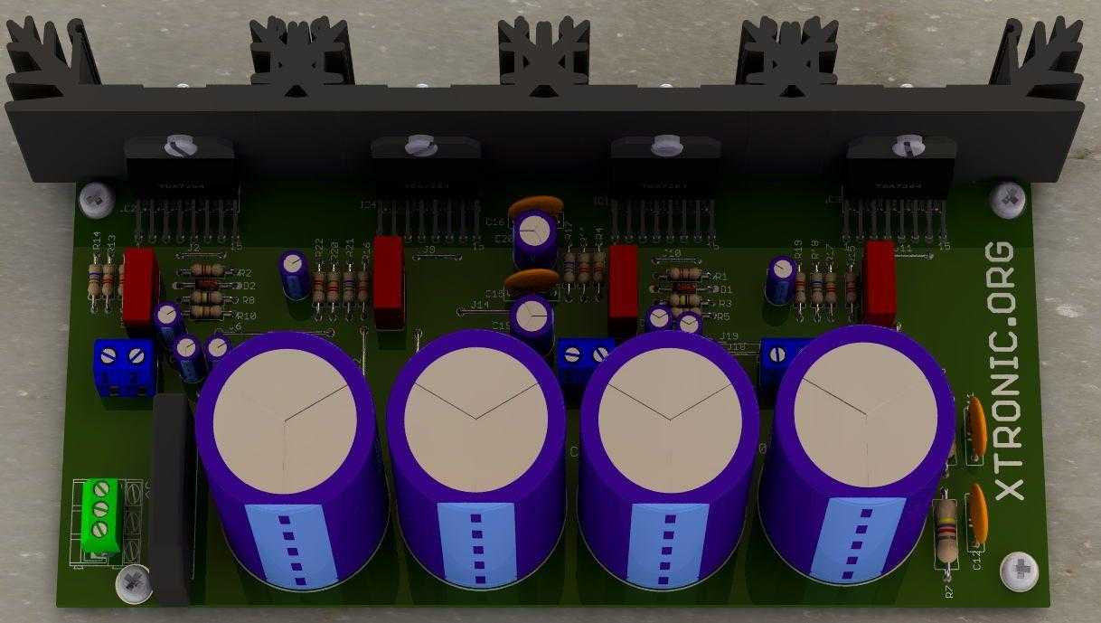
Suggested PCB mounting Brutus—bridged stereo amplifier 2 × 170 Watts (340 + watts total) – click in images to enlarge


About Brutus circuit assembly
The printed circuit board suggested for this assembly is a single face, to facilitate mainly the life of the beginners … however if it is a simple face there comes Jumpers! Connect pieces of wire, interconnecting the dots, paying attention to the thickness of the jumpers at the power connection points.
BOM to assemble the TDA7294 Brutus amplifier
Last update: 08/19/2021 22:24
| Part | Value | Description | Quantity |
| Capacitores | |||
| C1, C2, C11, C12, C17, C18 | 1µF/100V | Polyester capacitor | 6 |
| C3, C6, C7, C8, C13, C14, C21, C22 | 22µF/50V | Electrolytic capacitor | 8 |
| C4, C5, C9, C10 | 4.7000µF a 10.000µF | Electrolytic capacitor | 4 |
| C15, C16, C27, C28, C29, C30, C31, C32, C33, C34 | 100n/100V | Ceramic Capacitor | 10 |
| C19, C20 | 220µF/50V | Electrolytic capacitor | 2 |
| C23, C24, C25, C26 | 100nF/100V | Polyester capacitor | 4 |
| Semicondutores | |||
| D1, D2 | 1N4148 | Diodo | 2 |
| B1 | GSIB2580 or equivalent | Bridge rectifier | 1 |
| IC1, IC2, IC3, IC4 | TDA7294, TDA7295 or TDA7296 | Audio amplifier integrated circuit | 4 |
| Resistores 1/4W | |||
| R1, R2 | 27k | Red, violet, orange, gold | 2 |
| R3, R8 | 100k | Brown, black, yellow, gold | 2 |
| R4, R9, R11, R13, R15, R16, R17, R19, R20, R22 | 22K | Red, red, orange, gold | 10 |
| R5, R10 | 47k | Yellow, violet, orange, gold | 2 |
| R6, R7 | 4k7 /5W | Yellow, violet, red, gold | 2 |
| R12, R14, R18, R21 | 680 | Blue, gray, brown, gold | 4 |
| R23, R24 | 1 | Brown, black, gold, gold | 2 |
| Diversos | |||
| CN1 | AC | Terminal block 3 pin 5.08 mm | 1 |
| CN2 | INL | Terminal block 2 pin 5.08 mm | 1 |
| CN4 | ROUT | Terminal block 2 pin 5.08 mm | 1 |
| CN5 | LOUT | Terminal block 2 pin 5.08 mm | 1 |
| CN6 | INR | KK Male 2.54 mm 2-Way Connector KK | 1 |
| Solder, wires, printed circuit board, heat sink for the integrated circuits, thermal paste, bushing, screws, box, etc. | |||
Wait, here comes 2.1 amplifiers, stereo + subwoofer with TDA7294 and with TDA 7293.
Download the PDF files for assembling the Bridge stereo amplifier: Silk Screen, Copper PCB, PCB Component Side, Silk screen, TDA7294 Eagle Library, TDA7294 Datasheet.
Now includes Gerber file for you to order, uses printed circuit boards.
Download PDF
Mirror
To the bloggers who like to copy, please stop it, it is a lot of work to finish a project like this… so don’t be an “Ameba”, don’t copy! Link here, saying that you have a new circuit!!
- Datasheet PDF GSIB2580
- Datasheet PDF TDA7294
- Datasheet PDF TDA7295
- Datasheet PDF TDA7296
- Datasheet PDF TDA7293
Buy Diy kits TDA7294 in Aliexpress with free Shipping in the Worldwide.


Hello
I can’t able to download PDF plz send me on my mail.
[email protected]
Hello, link is ok!
Hello
I can’t able to download PDF plz send me on my mail.
Hello Prakash
Link is ok!
Sir give a PDF file please for download
Ahoj toni mam zdroj 29-0-29 muzu to pripojit ? Jinak dobře vypracovane schema libi se mi to. Dik moc za odpověd
its not work please help me
hi tony my compliments with the brutus project I have now also build him and just wonder if I can get rid of the hum of the diet you have an idea I would like to hear from you if you know a solution for it further am very happy with this project.
greetings gerard
Please give it’s finished circuit board photo
what’s dimension of pcb please reply sir
Hello Patael
17.7 x 8.3 cm; 6.96 x 3.27 inches
Can I use 30-0-30 7a and what’s dimension of pcb please reply sir
Hello Patael
Max 26-0-26 VAC
please make a 2.1 bridged amplifier using sta543sa ic
Hello
https://www.st.com/resource/en/datasheet/cd00061065.pdf
buenos dias alguien logro hacer este amplificador con respecto a las
R5, R6, R7, R10 47k
R12, R14, R18, R21 47k
como seria la configuracion correcta .. ? le prestamos atencion al circuito? o a lo que dejo toni en la lista de componentes ?
Hola Miguel
Ahora es correcto
Hai toni, Resistor R6, R7 4k7 or 47k?
4,7 KΩ/2w.not 47 kΩ.
Wledon, Tony. please, which software did you use in the design of the board and the 3d realization.
please Toni, what is the dimension of the board
hii toni i”ve make the project. but it’s not starting…… plz pllz help me
Hi,
I hv designsd this according to ur layout but my IC2 (the first one as on layout) got heated excessively !!! The circuit is working however but this particular positioned ic is heated up too high … I have tried replacing three ic’s in that position along wth the capacitors too but getting same problem… Plz help …
Ohh mr .Toni help me to get download file on these it ask for the password when I trying to open it in my phone please send them to my gmail without encrypted file
HI. Could you send me the PDF file as the link is not working? Thank you
Hi Alex
https://www.dropbox.com/s/00w83lo6vmnpg7y/tda7294%20est%C3%A9reo%20bridge%20te1.com.br_._xtroni.org.zip?dl=1
Hi Toni,
I builted brutus amplifier and it doesn’t work correct.
Once, I start the amplifier without load, it start increasing the temperature to the ics and bridge rectifier rapidly.
Please, I would like some to find the problem
Nick
greeted me, I have done according to your diagram, but it does not work, I do not know anymore why you can not tell me
Hi Mr Toni ,
Greetings to you and your family,
very interesting one ,
can u send me the Pdf files for the Pcbs , where iam not able to down load
Thanks in advance,
Sethu Ramachandran.
hi toni,
i made this… super amazing amp…
nice clearity & bass !
100000…thanks toni..
I like u so much.
Thanks,keep it up man.
(&i also made your another some circuits, all are success &great)
plz give your email id.
Toni I would like you to send for me pdf files for this project.
Am more interested in building this for my mini PA amplifier.
Thanks.
bonjour ne peux ouvrir en pdf merci envoyer dimensions du pcb.
salutations
hi, i made this amp but its not staring… should i know why it is not starting…
please…if possible could you design me a 5.1 channel circuit using the njw1186 processor…
if possible send me via my email [email protected]. PCB layout,part list n components layout will much be accepted
help me pdf file for this pcb sir
Sir.
the project is very nice and cool, i want to plead that you made a mistake listing the parts, the 22k resistor color code should be Red-Red-Orange not Red-Orange-Orange.
once again thanks for this projects….it quality is amazing.
Hi jeo. I like to make this amp. but I can’t understand this resistors, resistance R1,R2 it’s 47K or 4.7K
and this one R14 to R28 it’s 47K or 4.7K ??? please help me.
hello as scan the schematic diagram….the (R6,R7=4.7K 1/2 watt) (R12,R14,R18,R21=680 ohms 1/4 watt) (R5,R10=47K 1/4watt)………….before i will built also this project circuit…… email me at [email protected] what will be the outcome and result….
4.7k use only LED in PCB
Or 47k used for project
It is really !
R1,2 : 27 kΩ.
R3,8 : 100 kΩ.
R6,7 : 4,7 kΩ/2w.
R12,14,18,21 : 680Ω.
R4,9,11,13,15,16,17,19,20,22 : 22 kΩ.
R5,10 : 47 kΩ.
C1,2,17,18 : 1µF /250V – Polyester Capacitor.
C3,6,7,8,13,14,21,22 : 22µF/50V – Electrolytic capacitor.
C4,5,9,10 : 10.000µF/50V – Electrolytic capacitor.
C11,12,15,16 : 100nF /100V – Ceramic Capacitor.
C19,20 : 220µF /50V – Electrolytic capacitor.
B1 : VSIB2580, GSIB2580, D25XB60, GBJ2510.
D1,2 : 1N4148.
IC1,2,3,4 : TDA 7294.
Transformer : 230 V/2×18 V….2×26 V-8A.
Can u give me a complte details about this project i cant download the pdf thanks…
please send me the file
thank you
i am not able to download the PDF files for
Silk Screen, PCB, PCB component side, Silk screen, TDA7294 Eagle Library, TDA7294 Datasheet.
Would you mind to send me the file Via email ?
Thankyou very much.
i am not able to download the PDF files for
Silk Screen, PCB, PCB component side, Silk screen, TDA7294 Eagle Library, TDA7294 Datasheet.
Would you mind to send me the file Via email ?
Thankyou very much.
Hi Toni, Thanks for the wonderful post. I am planning to use this circuit for my Subwoofer but want to make some small changes in the PCB before doing so. Could you please send me the eagle files to my email. Thanks
Aravind
Hi Tony, can you send it to me … pleaseeeeeee :)
Hello,
I’m very interesting in this project,but I cannot download the PDF file in my area.Would you mind to send me the file Via email?
Thankyou very much !
Can you send me PCB for this amplifier TDA7294 2x150W
on this email [email protected]
could you send me the files please?
thnx alot
do you have stk 4050v pcb layout? can you pls. e-mail it to me
i am very interesting in this project but i cannot download the PDF file.would you mind to send me the file via e-mail?
Thank you very much.
I am not able to download the PDF files for
Silk Screen, PCB, PCB component side, Silk screen, TDA7294 Eagle Library, TDA7294 Datasheet.
Would you mind to send me the file Via email ?
Thankyou very much
I am not able to download the PDF files for
Silk Screen, PCB, PCB component side, Silk screen, TDA7294 Eagle Library, TDA7294 Datasheet.
Would you mind to send me the file Via email ?
Thankyou
I am not able to download the PDF files for
Silk Screen, PCB, PCB component side, Silk screen, TDA7294 Eagle Library, TDA7294 Datasheet.
Would you mind to send me the file Via email ?
Thankyou very much
hi
i want TDA7294 Datasheet and pcb width and height size.
please give
hi
i want tda7294 bridge 2x 170 Watts amplifier pcb Width and Height size.
please give me help me
hello
i want pcb hide and wide size
please say the size
i am not able to download the PDF files for
Silk Screen, PCB, PCB component side, Silk screen, TDA7294 Eagle Library, TDA7294 Datasheet.
Would you mind to send me the file Via email ?
Thankyou very much.
hi Toni,
Nice project.
i am not able to download the file, can you send it me over mail?
Thank you very much in advance
hi Toni,
i am not able to down load the file, can you send me the file Via email ?
Thankyou very much
it works great. thanks
Can we again bridge the two channels left and right for subwoofer application, Please suggest.
If so please help me to understand how to bridge the two channels to a single output with total 300+ watts.
Hi Raj
http://www.te1.com.br/2011/04/circuito-amplificador-audio-dinamico-tda7294-bridge-estereo/
I am not able to download the PDF files for
Silk Screen, PCB, PCB component side, Silk screen, TDA7294 Eagle Library, TDA7294 Datasheet.
Would you mind to send me the file Via email ?
Thankyou very much
Hi Raj sent!
urgent merci de m’envoyer les documents en pdf que je ne peux ouvrir sur votre site cela bloque ma décision de construire cette maquette merci
good luck .
any one try this if try then show me ur pic
thanks
Hello,
I’m very interesting in this project,but I cannot download the PDF file in my area(HongKong).Would you mind to send me the file Via email ?
Thankyou very much !
KC.Yung
sent
Good luck
need pdf files pliz
hi toni