Table of Contents
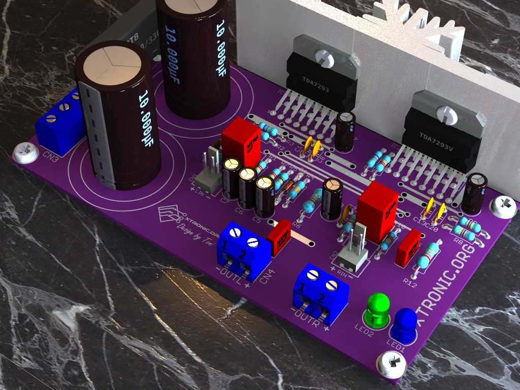
TDA7293 amplifier circuit diagram with PCB 2x 100W. Amplifier circuit stereo audio with good power, using integrated circuit TDA7293 for up to 2x 100 Watts. With Suggested PCB mounting design. Includes power supply to the circuit itself, thus only requires a transformer to power. PCB compact size, even being single sided. Allowing mount a power amplifier and compact with good quality, ideal for various applications.
Includes power supply on board, only requires a transformer to power the circuit.
The part of the power supply uses bridge rectifier, large electrolytic capacitors to filter values can be used since the 4.700μF to 12.000μF. The LEDs, in series with the resistor and indicate on state, serve to discharge the electrolytic capacitors.
Includes circuit mute / stand-by, but was not placed key to turn on and off, is to avoid clicks in the speakers on and off, being unnecessary to use the relay output.
The power transformer can be from 18-0-18 to 33-0-33 / 200VA, with transformer with lower voltage may need less current too.
The integrated circuit body should be insulated from the heatsink using mica or plastic thermal pad to insulate the screw.

About the TDA7293 amplifier circuit diagram with PCB
This is another application for this versatile integrated circuit that allows simple bridge and parallel mounting. This time we present the stereo version. This circuit also has good sound quality and protection against overheating and short circuits.
It includes a power supply on the board, requiring only a transformer to power the circuit.
The source part uses a rectifier bridge, large electrolytic capacitors for filter, values from 4,700µF to 10,000µF can be used. The leds in series with the resistors not only indicate the on state, but also discharge the electrolytic capacitors.
The mute/stand-by circuit is included, although no key was placed to activate and deactivate it, but it serves to avoid clicks in the speakers when turning them on and off, making it unnecessary to use a relay in the output.
The board design has close tracks, so be careful when “fabricating” your PCB, to check for possible shorts.
The transformer can be from 12-0-12 to 28-0-28, with a lower voltage transformer you may need less current too! For transformer related calculations, see this article. To see a graph of power vs voltage ratio, check the PDF datasheet of the IC.
Capacitor C2 and C23 form the AC coupling for our amplifier and with R1 and R10 form a high-pass filter circuit, influencing mainly the low frequencies (bass). Using a 470nF capacitor according to the datasheet we have a cut-off at about 15Hz, and if a 1uF capacitor (our case) is used we have a cut-off at about 7Hz. For a 2.2uF capacitor, we have 3.2Hz.
The formula is f = 1/(2ΠRC)
The resistor R15 /C21 and R4 /C22, form a low-pass filter to keep high-frequency signals away from our power amplifier. For the values used, we have a cutoff at about 400 KHz. If you prefer, change the components with larger values and lower the cutoff frequency.
The formula is f = 1/(2ΠRC)
The mute circuit was implemented according to the circuit available in the datasheet, and capacitors C5 and C6 together with R5 and R7 are responsible for the time constant when switching the amplifier on and off and avoiding “pop”.
Resistors R11-R13 and R2-R3 are responsible for the gain and in the circuit configuration they are set to 30 dB, you can change these components to alter the gain. However, make sure that R11-R2 is the same value as R13-R3.
The resistors R1-R10 are the ones that determine the input impedance of the amplifier.
The circuit formed by R6-C4 and R12-C16 is a Boucherot cell, also known as a Zobel net. A Zobel net helps prevent oscillation that can occur in parasitic induction of the long speaker wires. It also acts as a filter to prevent radio interference coming through the speaker wires from reaching the inverter input of the amplifier through the feedback loop.
Capacitors C7 and C19 are for DC decoupling of the feedback circuit, if you prefer to use larger values to improve bass response. Capacitors C3 and C17 are for bootstrapping and have different position for TDA7293 compared to TDA7294, TDA7295 and TDA7296. On the PCB, it is indicated as 93/94.
Table of CIS that can be used in our TDA7293 Amplifier and equivalent.
| CI | TDA7293 | TDA7294 | TDA7295 | TDA7296 |
|---|---|---|---|---|
| Maximum power | 100W | 80W | 60W | 50W |
| Maximum voltage at 4 Ohms* | 33VDC | 30V DC | 26VDC | 22VDC |
| Maximum voltage at 8 Ohms* | 40VDC | 38VDC | 35VDC | 30VDC |
*Dual power supply, stereo mount.
Schematic TDA7293 amplifier circuit diagram with PCB

Suggested PCB layout


BOM for mounting tda7293 stereo
Last Update: 09/11/2021 18:24
| Part | Value | Description | Quantity |
| Capacitors | |||
| C1, C4, C8, C13, C16, C20 | 100nF/100V | Ceramic Capacitor | 6 |
| C2, C23 | 1µF/63V | Polyester Capacitor | 2 |
| C3, C5, C6, C17 | 22µF/63V | Electrolytic capacitor | 4 |
| C7, C19 | 47µF/63V | Electrolytic capacitor | 2 |
| C9, C11 | 10.000µF/63V | Electrolytic capacitor | 2 |
| C21, C22 | 220p/100V | Ceramic Capacitor | 2 |
| Semiconductors | |||
| D1 | 1N4148 | Diode | 1 |
| IC1 | TDA7293, TDA7294 or TDa7295, or TDA7296 | Audio amplifier integrated circuit | 2 |
| B1 | GBJ3510, GBJ2510 or equivalent | Bridge rectifier | 1 |
| LED1, LED2 | Led 5MM | Red LED or color of your choice | 2 |
| Resistors 1/4W | |||
| R1, R2, R7R10, R11 | 22K | Red, red, orange, gold | 4 |
| R3, R13 | 680 | Blue, gray, brown, gold | 2 |
| R4 | 33k | Orange, orange, orange, gold | 1 |
| R5 | 10k | Brown, black, orange, gold | 1 |
| R6, R12 | 2,7 ohm 1 Watt | Red, violet, gold, gold | 2 |
| R8, R9 | 4,7K | Yellow, violet, red, gold | 2 |
| R14, R15 | 1,8K | Brown, black, red, gold | 2 |
| Miscellaneous | |||
| CN1 | LIN | Jst Xh 2-Way Connector 2.54 mm pitch or equivalent | 1 |
| CN2 | RIN | Jst Xh 2-Way Connector 2.54 mm pitch or equivalent | 1 |
| CN3 | AC | Terminal block 3 pin 5.08 mm | 1 |
| CN4 | OUTL | Terminal block 2 pin 5.08 mm | 1 |
| CN5 | OUTR | Terminal block 2 pin 5.08 mm | 1 |
| Solder, Wires, PCB, housing, connectors, insulation for the CIS, heatsink, etc. | |||
Download PDF files of this assembly: TDA7293 datasheet, copper side plate, component side.
Gerber added
- IC TDA7294 datasheet PDF — Updated
- GBJ3510 rectifier bridge datasheet in PDF
- PDF Datasheet rectifier bridge GSIB2580
- IC TDA7295 PDF Datasheet
- IC TDA7296 PDF Datasheet
- IC TDA7293 PDF Datasheet
Buy kits TDA7293 in AliExpress with free Shipping in the Worldwide.


Hi Toni do u have Gerber file
Hello Baskar
https://www.dropbox.com/s/cdmf37ixjzv2qo0/tda7293-estereo-te1.com.br.zip?dl=1
Hallo sir Toni,
I want to join your FB group….Is it possible..??
Hello,
Do you have gerbers for this PCB?
Thank you,
David in London
hi toni, some parts are missing and some are wrong values.r5,r15 on part list is 100k on sematis is 10k.c 21,c22 is not on part list 220pf.r4,r14 on part list 27k on shematic is 33k.R7, R16 on part list 33k on sematic is 22k.
hi, toni c21 and c22 missing on part list 220pf.in part list r5 and r15 is 100k on shematic is 10k.
Hello aleksandar
Is there noise even without signal at the input?
Hi
c22? missing
r5, r15 10k or 100k
Hola consulta
Calienta mucho los IC, uno calienta más que el otro, el canal L calienta más que el R
Por qué puede ser??
Hola Agustín
Uses thermal pad?
See the jumper!
Sir,please tell me that 100nf and 1uf capacitor are how much volt
HI Kamal
50V to 100V
Good morning, I wanted to know kindly the input power of the amplifier how many volts? Thanks, I am waiting for an answer
Hello Fabrizio
Input sensitivity about 300mV.
Hello I was just wondering what are the dimensions for the PCB?
Hello Felix
10.8 x 7.2 cm; 4.25 x 2.84 inches
And I wanted to ask how much Ω must the speakers have to operate.
Hello Andreas
4 at 16 Ohms.
Hello,
I had some questions about this circuit:
1. Which speakers can I use on the output,A tweeter or an woofer?
2. Is the output of these anolog or digital?
3.If you could send me the pcb Files from EAGLE.
Hello Andreas
1 – An Woofer full range or Woofer + tweeter
2 – Analog
3 – Send me a e-mail!
And whats is your e-mail?
Hello Andreas
do the test
Can you give me the EAGLE file from that circuit diagram in the .sch form?
https://www.te1.com.br/contato/
I assembled this circuit but when I give power it works few seconds and no sound. Can you help me out. Power transformer is 24-24 1-1 ampier
Hello Raj
Use at least 3A.
Dear sir,
Im expecting to get pre-amp with 2 microphone input circuit?
Hello K.Senevirathna
Coming soon, wait!
РУССКИЙ
каковы размерыкаковы размеры печатной платы29 / 10000
АНГЛИЙСКИЙ
Перевести вGoogleBing
what are the dimensions of the PCB
Hello Kirill
10.8 x 7.2 cm
Hi bro,
What is AC voltage value plz tell me.
Dear Toni
Can you give me circuit for a preamplifier
Thank you,
What should the dimensions of the PCB be? Or is the image set to the right size already?
Hi. I have question about the transformer. I have one where i have 24V AC but i don’t have a GND. Where can i get GND? Can i make it by myself or i must buy transformer with it?. Thanks.
Can i use it for subwoofer
Hello, the circuit is great! but I have doubts about the transformer, i can buy 18,0,18 V or 24,0,24 V transformers, but the only thing i know is the max output current. Is it ok if i calcuate 200VA/36V=5,5A(for the 18V one) and 200VA/48V=4,1A (for the 24V one)?
Cho em hỏi mạch này đổi TDA 7293 thành TDA 7396 được k ạ?
Hello Trần văn trà
TDA7396 is different!
Here’s a project with this CI!
https://easyeda.com/horvatnor24o/Tda7396-qrlfxP7pH
Can I use this 200 watt in 1 side and other 1 PCB for 2 side mean left side speaker for 1 PCB and 2 Right side for 1 pcb
Want a 3 way system?
yes, one pcb for subwoofer and one pcb for two speakers
Hi can I use 200 watt in 1. I mean left side speaker and other 1 PCB for right side plz reply as soon as
Hello dears.
I have tda7294. I can use this ic instead tda7293?
Any change need it?
Hello Nima. I saw recently some ciruits and it seems, that tda7294 is usable, but you might Add or take one capacitor of ciruit. Cant remember, fell free to search the web.
Hello dears.
I have tda7294. I can use this ic instead tda7293?
hi toni
sir ic is small but in pcb see u ic place is big pllz help me about this
hi
bro
pcb is not fit on ic. ic is small but in pcb
ic is big any i help me
Sir,pls give tansister BC 548 using preamplifier circuit for IC tda 7294
Pls, give me preamplifier circuits using BC 548 transistor
+918626079920 for help to design your own pcb at home like that
ME PARECE BIEN
cual es el propósito con los circuitos de audio hay otros que interesen o que sean mas industrial
esa es una forma de informarse bien espero que sigan asi proporcionando ideas pronto nos comunicamos
que estén bien Sres
Hi toni
very good design with power supply on board
i’ll ride it as soon as possible .is 5 amp enough for ?
thanks .
where can i buy the whole PCB and component of this audio amp. i myself will assemble it. please help me i am very much interested in this stuff..thank you very much
You can assemble this pcb at home i can help u +918626079920
i want a pcb where i can get in india
please tell me address
matey can you suply circit boards only I will populate them my self and how much delivered to australia
send me.tk
I have no any idea or experiance about this all.but i want to learn to build it self.truly i,m most lover of this simple circuit amp controller and most for high watt capasity.so guy, i cant build it and wont make any deal with china.you all know it why,.well if somebody agree and want sell own project (finish good) to me should reply me on [email protected].
No metter what of value been set by you.
Deal guys.good conditions for good price.
BOOOM LOVER
Can you send the pcb files are up to date
Via email
I’ve tried but did not succeed to make no sound